background image

15

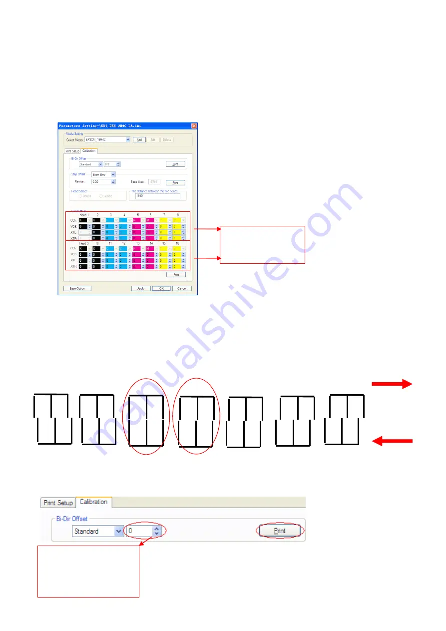
3. Color offset: Color offset is to align all color in order to print good quality images.

Tip: Based on the "0" position, the color lines should totally matched with the Black line, if not, find the best one

showing on the printed out color offset, then input the corresponding values in the software. Note that values are

accumulated.

If the "0" position is not the perfect matching one, then we have to adjust the figure on the software. Go to

Option

Option

Option

Option

Calibration

Calibration

Calibration

Calibration

Color

Color

Color

Color Offset

Offset

Offset

Offset

After input the value, print the alignment again. And observe if the "0" position is the best or not. If not, repeat the

above procedure until the best result come out.

4.

4.

4.

4.

4. Bi-Dir offset

Bi-Dir offset is to make sure there is no bi-difference while using different speed to print. Bi-Dir offset will be done

while the printing speed changed.

If the "0" position is not the perfect matching one, then we have to adjust the figure on the software. Go to

Option

Option

Option

Option

Calibration

Calibration

Calibration

Calibration

-

Bi-Dir

Bi-Dir

Bi-Dir

Bi-Dir Offset

Offset

Offset

Offset

Values are input here.

Input the value here. This

value is accumulated. Press

Print

to print the test

pattern.

0

4

OK

NG

-4

-8

8

16

-16

Содержание DX5 X 2

Страница 1: ... X X X 2 2 2 2 Printheads Printheads Printheads Printheads Calibration Calibration Calibration Calibration and and and and Maintenance Maintenance Maintenance Maintenance 31 31 31 31st st st st Jan Jan Jan Jan 201 201 201 2013 3 3 3 Version V3 0 ...

Страница 2: ...tallation 4 Chapter 3 Characteristic 5 Chapter 4 Board System 6 Chapter 5 Software Installation 7 Chapter 6 Software Interface 9 Chapter 7 Software Calibration 10 Chapter 8 Other Functions and Parameters 17 Chapter 9 Maintenance 19 Chapter 10 Troubleshoot 24 Chapter 11 Output Chart 25 ...

Страница 3: ...perating system Microsoft Windows 2000 XP 2 2 2 2 Recommendatory Recommendatory Recommendatory Recommendatory requirement requirement requirement requirement CPU 3 0 GHz or higher Memory 2 Gb or higher Hard disk 200 Gb or higher NTFS format Mother board USB connection equipped Network card Operating system Microsoft Windows 2000 XP NOTICE NOTICE NOTICE NOTICE Suggest user format your hard disk int...

Страница 4: ...r The grounded voltage should not be more than 0 3V and the grounded resistance should be less than 3Ω 8 Connect the USB cable between printer and computer Check if the wires and data cables are plugged in properly 9 Install the output and the rip software 10 Move the carriage to middle of printing platform turn on the printer let the carriage move to home position and keep your hand on the emerge...

Страница 5: ...continuously or print different image continuously Automatically flash jetting Automatically clean printheads by flash jetting during printing Home flash jet Prevent nozzles of printheads block while not in printing state Color bar Prevent nozzles clogging and observe nozzles status Able to set the width of color bar and the instance from image Able to align printheads step difference and bi direc...

Страница 6: ...board Mainboard Mainboard Mainboard Encoder sensor Magnetic sensor Processing Indication Optical Fiber plug Printhead cable plug 1 Power flat cable plug X Driver DB plug Power cable Plug Y Driver DB plug Pump plug Power supply plug USB data port Processing Indication Optical Fiber plug Status LED Power LED Status LED Power LED Printhead cable plug 2 Control panel plug ...

Страница 7: ...RROR LED is off only on when there is problem Chapter Chapter Chapter Chapter 5 5 5 5 Software Software Software Software Installation Installation Installation Installation This software consist of printer driver printing adjustment and picture printing functions Please follow the following steps to install the software 1 Turn on the computer till the system is ready copy UDT_PrintExp UDT_PrintEx...

Страница 8: ...uter and turn on the machine Look for PrintDrv_new PrintDrv_new PrintDrv_new PrintDrv_new file file file file in the folder of UDT_PrintExp UDT_PrintExp UDT_PrintExp UDT_PrintExp It shows as above after finished installing the control software ...

Страница 9: ...h Flash Flash Flash jetting jetting jetting jetting function function function function status status status status Carriage Carriage Carriage Carriage position position position position Configuration Configuration Configuration Configuration definition definition definition definition UDT_DX5_ UDT_DX5_ UDT_DX5_ UDT_DX5_2 2 2 2H4C_LA H4C_LA H4C_LA H4C_LA LA model with 1 printheads UDT_DX5_ UDT_DX...

Страница 10: ... function function before before before before doing doing doing doing the the the the alignment alignment alignment alignment Base on the Head Status diagram to adjust vertical position between two printhead The setting is at Option Calibration The distance between the two heads Case 1 Have to increase the value between the two heads Case 2 Have to decrease the value between the two heads 2nd pri...

Страница 11: ...step to adjust 1st printhead vertical alignment individually Face carriage the left one is 1st printhead 2 Then follow the following step to adjust 2nd printhead vertical alignment Face carriage the right one is 2st printhead 3 After finish both printhead vertical alignment adjust 2nd printhead horizontal position to change the space between two printhead Space between two printhead is 1 nozzle pr...

Страница 12: ...e need to adjust the carriage plate There are 3 situations 1 The two pass is perfectly aligned no need to adjust No need to adjust 2 The second is on the left side of the first pass Adjust method 3 The second is on the right side of the first pass A Loosen the 3 screws on the carriage plate B Turn the screw clockwise First pass Second pass First pass Second pass First pass Second pass ...

Страница 13: ...arriage carriage carriage carriage plate plate plate plate Keep Keep Keep Keep adjusting adjusting adjusting adjusting until until until until the the the the second second second second pass pass pass pass is is is is perfectly perfectly perfectly perfectly aligned aligned aligned aligned with with with with the the the the first first first first pass pass pass pass Moreover after adjust the pri...

Страница 14: ...inish adjustment print vertical status to check again and make sure both printheads vertical are aligned 2nd printhead 2nd printhead Loosen the 3 screws on the carriage plate adjust both screw at same time to move the 2nd printhead forward and backward There is no overlap or separate between two printhead ...

Страница 15: ... Offset Offset Offset Offset After input the value print the alignment again And observe if the 0 position is the best or not If not repeat the above procedure until the best result come out 4 4 4 4 4 Bi Dir offset Bi Dir offset is to make sure there is no bi difference while using different speed to print Bi Dir offset will be done while the printing speed changed If the 0 position is not the per...

Страница 16: ...ile while while while adjusting adjusting adjusting adjusting the the the the step step step step offset offset offset offset Adjust Adjust Adjust Adjust to to to to get get get get the the the the best best best best step step step step value value value value Then Then Then Then test test test test print print print print to to to to see see see see whether whether whether whether there there th...

Страница 17: ...mally the voltage function is not being used The range of adjusting voltage is 42V to 1 3V 2 2 2 2 Other Other Other Other function function function function Click Option on the main interface of the software it shows the following window Details of the print option 1 1 1 1 Flash Flash Flash Flash Jetting Jetting Jetting Jetting frequency frequency frequency frequency You could set the flash jett...

Страница 18: ...on Feather function function function function To blur the pass line feather pass edge 1 Option Enable Disable the feather function 2 Type of Eclosion 3 Value of Eclosion 4 4 4 4 Color Color Color Color Bar Bar Bar Bar 1 Distance mm Setup for distance between the color bar and the picture 2 Width mm Setup for the width of the whole color bars 3 Setup for the position of color bar in the right left...

Страница 19: ...nnect the damper put the other side of the extend tube into the appointed Flush Choose Depth clean mode to clean the damper and the printhead at the same time 3 times 3 Take out the extend tube from the Flush and keep it out in the air Choose Depth clean mode to suck out the Flush inside the damper and the printhead After that connect the damper to the ink incoming tube and fill ink again 4 Test p...

Страница 20: ...rd clean mode to empty the ink in the damper 2 times 2 Use a extend tube to connect the damper to the appointed Flush Choose Depth clean mode to clean the damper and the printhead at the same time 2 times 3 Take out the extend tube from the Flush and keep it out in the air Choose Depth clean mode to empty the Flush inside the damper and the printhead Use the tube cover to seal the ink incoming tub...

Страница 21: ...the same time Clean one color at a time use a cap to cover other three color channel 4 Take out the extend tube from the Flush and keep it out in the air Choose Depth clean mode to empty the Flush inside the damper and the printhead 5 Take out the four tubes K C M Y from the cartridge Use the extend tube to connect them to flush ...

Страница 22: ...se Ink Fill mode at control panel use ink pump to flush ink tube until it is clear Then take out the tube from the Flush choose Ink Fill mode empty the Flush inside the ink tube Clean K C M Y tube one by one After cleaning use cap and fresh warp to seal the ink tubes ...

Страница 23: ...ke out four cartridges use fresh wrap to seal the ink supply hole and keep the cartridges in the proper place 7 Keep the carriage back to Home position and make sure the cap is perfectly sealing the printhead ...

Страница 24: ...ng during during during printing printing printing printing 1 Check whether the X motor belt and the gear is loosened or damaged 2 Check the X motor 3 Check whether the encoder is dirty or scratched 4 Check whether the encoder sensor is dirty or defective 5 Keep a distance from strong magnetic field Prevent using instable input power Equip a UPS and stabilizer 10 5 10 5 10 5 10 5 Error Error Error...

Страница 25: ...e high speed level There is tolerance in different computers Output Output Output Output Chart Chart Chart Chart Printhead Epson DX5 Number of Printhead 2 Output Print Mode Fast mode output m2 h 1 6m 1 8m 2 1m 2 5m Draft 4Pass 28 31 34 35 Standard 6Pass 20 21 22 24 Quality 8Pass 14 16 17 18 High Quality 8Pass 14 16 17 18 Back lit 12Pass 7 8 10 12 ...

Отзывы: