Epson AN2WA87 Скачать руководство пользователя страница 12

AN2 Series

Installation Instructions

12

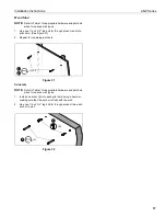
Pitch Adjustment (Vertical Elevation)

Adjust projector so that the top and bottom horizontal lines of
the test pattern are parallel with each other and with top and
bottom of whiteboard.

1.

Loosen pitch adjustment locking screw using a #2 Phillips
screwdriver. (See Figure 15)

2.

Turn pitch micro-adjustment screw right or left using a #2
Phillips screwdriver until image is properly aligned on target.

3.

Tighten pitch adjustment locking screw using a #2 Phillips
screwdriver.

Figure 15

Micro Adjustment

IMPORTANT ! :

The projected image should NEVER

project onto the whiteboard frame. An image overlapping
onto the whiteboard frame may prevent the projector
touch sensor from working properly.

1.

If required, turn the micro adjust fastener

clockwise

to

extend projector further from wall. (See Figure 16)

2.

If required, turn the micro adjust fastener

counterclockwise

to retract projector closer to wall.

Figure 16

Installing Control Pad

1.

Open lower cover on control pad (included with projector).
(See Figure 17)

2.

Insert control pad into control housing (EE) by sliding it up
under tabs inside housing. (See Figure 17)

Figure 17

1

3

2

2

2

1

 Extend

Retract

2

1

(EE)

Control
pad

Tabs

Содержание AN2WA87

Страница 1: ...I N S T A L L A T I O N I N S T R U C T I O N S Epson All in One Collaborative Whiteboard AN2 87 and 100 AN2 Series ...

Страница 2: ...installed using the instructions provided WARNING Failure to provide adequate structural strength for this component can result in serious personal injury or damage to equipment It is the installer s responsibility to make sure the structure to which this component is attached can support five times the combined weight of all equipment Reinforce the structure as required before installing the comp...

Страница 3: ...Installation Instructions AN2 Series 3 DIMENSIONS DIMENSIONS INCHES MILLIMETERS AN2 87 DIMENSIONS INCHES MILLIMETERS AN2 100 ...

Страница 4: ... Chave de bocas Chiave a punte aperte Steeksleutel Clé à fourche By Hand A mano Von Hand Com a mão A mano Met de hand À la main Hex Head Wrench Llave de cabeza hexagonal Sechskantschlüssel Chave de cabeça sextavada Chiave esagonale Zeskantsleutel Clé à tête hexagonale Pencil Mark Marcar con lápiz Stiftmarkierung Marcar com lápis Segno a matita Potloodmerkteken Marquage au crayon Drill Hole Perfora...

Страница 5: ... 2 4 24 x 1 4 HH 1 Marker kit EE 1 FF 1 Marker tray C 1 Left valence bracket D 1 Right valence E 1 Valence NN 1 IR Cable Control panel assembly BB 4 Toggler AF6 MM 5 Whiteboard bracket Upper wall bracket B 1 Wall hanging bracket bracket 9200 003827 9200 003805 9200 003817 F 4 1 4 20 x 1 3 4 G 4 1 4 M 4 10 24 x 3 8 N 1 Boom spacer P 1 5 16 Q 1 5 16 U 1 Sensor cover V 4 M4 x 12mm X 4 10 24 x 1 3 4 Y...

Страница 6: ...ill one pilot hole see Table 1 for size at location marked in Step 3 See Figure 1 and follow fastener information appropriate for wall type located in Table 1 IMPORTANT See Fastener Installation Methods at end of Installation Instructions for details on installing product into various wall types Table 1 Fastener Information WALL TYPE PILOT HOLE FASTENERS see PARTS drawing Drywall only boom attach ...

Страница 7: ...t over studs See Figure 4 NOTE For wood or steel stud walls mark at least two locations for attachment a minimum of 16 apart and a maximum of 24 apart AND within slots on wall bracket assembly NOTE For concrete walls mark at least two locations for attachment a minimum of 16 apart AND within slots on wall bracket assembly 7 Drill one pilot hole see Table 1 for size at each location marked in Step ...

Страница 8: ...ips machine screws X and refasten projector mount to boom arm See Figure 5 5 AN2 100 Only Turn adjustment bolt to move projector mount towards end of boom arm until front of adjustable plate lines up with 100 marking on boom arm See Figure 5 6 Hang boom projector mount S over bolt on wall bracket assembly and loosely fasten hand tighten using boom spacer N 5 16 washer P and 5 16 nut Q See Figure 6...

Страница 9: ...bly is attached 3 3 S Wall bracket assembly 2 PP x 4 5 4 Center whiteboard assembly on wall bracket NOTE Notch in wall bracket assembly indicates center of whiteboard 5 Level the whiteboard against the wall by placing a level against the front of it and adjusting the leveling feet See Figure 7 6 Continue to adjust until whiteboard is leveled with the wall 7 Remove and keep one fastener from bottom...

Страница 10: ...igure 11 4 Add and route cables following instructions included with the projector NOTE Do NOT place extra cable length behind the sensor bracket Figure 11 5 Place a level on top of the boom arm mount and level the mount after the projector is installed See Figure 12 5A Tighten nut to increase boom arm angle 5B Loosen nut to decrease boom arm angle 6 Place a level on top of interface T and level S...

Страница 11: ...hat the left and right vertical lines of the test pattern are parallel with each other and each side of whiteboard 1 Loosen ROLL adjustment locking screw using a 2 Phillips screwdriver See Figure 13 2 Turn ROLL micro adjustment screw right or left using a 2 Phillips screwdriver until image is properly aligned on target 3 Tighten ROLL adjustment locking screw using a 2 Phillips screwdriver Figure 1...

Страница 12: ...crewdriver Figure 15 Micro Adjustment IMPORTANT The projected image should NEVER project onto the whiteboard frame An image overlapping onto the whiteboard frame may prevent the projector touch sensor from working properly 1 If required turn the micro adjust fastener clockwise to extend projector further from wall See Figure 16 2 If required turn the micro adjust fastener counterclockwise to retra...

Страница 13: ...lling Control Housing 1 Open door on control panel assembly EE 2 Insert edges of control panel assembly EE into groove in whiteboard frame with tab placed behind whiteboard See Figure 19 3 Slide control panel assembly up along side of whiteboard to the desired height See Figure 19 4 Determine attachment location on wall See Figure 19 5 Mark attachment hole through slot in control panel assembly EE...

Страница 14: ...aching Valence 1 Align right valence bracket D along outside of right brace on back of valence E and fasten with two 10 24 x 1 4 Phillips pan head machine screws L See Figure 21 2 Align left valence bracket C along outside of left brace on back of valence E and fasten with two 10 24 x 1 4 Phillips pan head machine screws L See Figure 21 3 Slide the valence E with attached brackets into the boom pr...

Страница 15: ...or Cover and Outer Cover 1 Reattach the sensor cover using the fastener previously removed See Figure 2 Figure 24 2 Hold sensor outer cover U under boom projector mount and begin sliding downward toward top of whiteboard See Figure 25 3 Continue sliding cover downward until tabs at bottom of cover slip into slot on top of whiteboard See Figure 25 Figure 25 Attaching Marker Tray 1 Attach marker tra...

Страница 16: ... wall until flange of cap is flush with wall See Figure 28 Figure 28 4 Snap off plastic straps on anchor at wall by pushing side to side snapping off straps level with flange of plastic cap See Figure 29 Figure 29 5 Line up anchor with attachment point 6 Insert 1 4 20 x 1 3 4 Phillips pan head screw F through 1 4 washer G corresponding mounting hole in product and into anchor H and tighten until f...

Страница 17: ...t and into pilot hole See Figure 31 2 Repeat for remaining pilot hole Figure 31 Concrete NOTE Refer to Table 1 for appropriate hardware and pilot hole sizes for various wall types 1 Install an anchor K into each pilot hole using a hammer making sure that the anchor is flush with the wall 2 Use one 1 4 x 2 1 2 lag bolt J through product into each anchor in wall Figure 32 1 2 J x 2 1 2 J K ...

Страница 18: ...AN2 Series Installation Instructions 18 ...

Страница 19: ...Installation Instructions AN2 Series 19 ...

Страница 20: ... North Detroit Street Warsaw IN 46582 P 574 267 8101 or 800 622 3737 F 574 267 7804 or 877 325 4832 E info da lite com www milestone com 2015 Milestone AV Technologies LLC AN2 Series Installation Instructions 8800 002671 Rev02 06 15 ...

Отзывы: