EPSON Stylus COLOR 900/900N
Chapter 4 Disassembly and Assembly
93
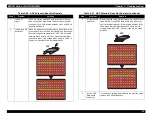
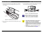
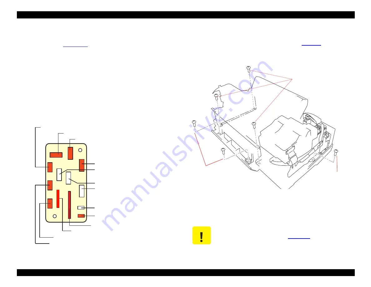
4. Unlock the remaining cable clip (it secures the control panel FFC),
and then disconnect the following connectors from the relay board
(shown in red in
CN8: 12-pin FFC for the control panel
CN18: 19-pin FFC (powers sensors and transmits detection
signals)
CN11: 2-pin connector for driving the solenoid
CN6: Connector for ASF
CN13: Connector for PF motor
CN12: Connector for Pump/ASF motor
CN7: Connector for PE sensor
CN14: Connector for CR motor
CN5: Connector for CRHP (Carriage Home Position) sensor
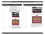
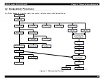
Figure 4-5. Connector Locations
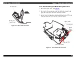
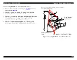
4.2.3 Printer Mechanism Removal
1. Disconnect the main wiring harnesses. (See
2. Remove the two screws securing the waste ink drain pad cover to
the lower case, and then remove the drain pad cover.
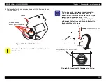
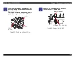
Figure 4-6. Removing the Printer Mechanism
3. Remove the four large screws securing the printer mechanism to
the lower case, and then remove the printer mechanism.
M / C
M/
C
CRH
P
E
A
S
F
RE
D
WH
T
BL
K
M/
C
C R M o t o r
P u m p / A S F M o t o r
C R H P S e n s o r
P E S e n s o r
A S F S e n s o r
f r o m C N 1 1 o n t h e m a i n b o a r d
f r o m t h e c o n t r o l p a n e l
f r o m C N 1 2 o n t h e m a i n b o a r d
P F M o t o r
f r o m C N 1 0 o n t h e m a i n b o a r d
f r o m C N 1 6 o n t h e m a i n b o a r d
S o l e n o i d
f r o m C N 1 5 o n t h e m a i n b o a r d
C A U T I O N
After replacing the Waste Ink Pads, perform any
necessary adjustments. (See
.)
Screws securing the
Waste Ink Drain Pad Cover
Screw securing
the Printer
Mechanism
Screws securing the
Printer Mechanism
Содержание 900N
Страница 1: ...EPSONStylusCOLOR900 900N Color ink jet printer TM SC900 N 6 59 0 18 ...
Страница 8: ... 37 5 PRODUCTDESCRIPTION ...
Страница 37: ... 37 5 OPERATINGPRINCIPLES ...
Страница 67: ... 37 5 TROUBLESHOOTING ...
Страница 89: ... 37 5 DISASSEMBLYANDASSEMBLY ...
Страница 121: ... 37 5 ADJUSTMENTS ...
Страница 156: ... 37 5 MAINTENANCE ...
Страница 169: ... 37 5 APPENDIX ...
Страница 178: ...EPSON Stylus COLOR 900 900N Chapter 7 Appendix 175 7 3 Component Layout Figure 7 2 C265 Main Board Component side ...
Страница 179: ...EPSON Stylus COLOR 900 900N Chapter 7 Appendix 176 Figure 7 3 C265 Main Board Soldering side ...
Страница 180: ...EPSON Stylus COLOR 900 900N Chapter 7 Appendix 177 Figure 7 4 C265 PSB Board Figure 7 5 C265 PSE Board ...
Страница 181: ...EPSON Stylus COLOR 900 900N Chapter 7 Appendix 178 Figure 7 6 C265 PNL Board ...
Страница 195: ...06 03 01 02 for S E ASIA 03 03 05 03 04 EPSON STYLUS COLOR 900 No 7 10056 Rev 01 ...
Страница 197: ......
Страница 198: ......
Страница 199: ......
Страница 200: ......
Страница 201: ......


