Installation
MVP3G-M/2/5
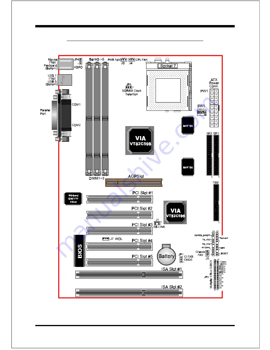
Page
4
Figure 1
MVP3G-M/2/5 Detailed Layout
Страница 1: ...cifications are subjected to change without notice Manual Revision 10 0 July 14 1999 ISA PCI AGP Motherboard with Onboar Onboar Onboar Onboar Onboard PCI IDE and Super d PCI IDE and Super d PCI IDE and Super d PCI IDE and Super d PCI IDE and Super Multi I O Multi I O Multi I O Multi I O Multi I O MVP3G M MVP3G2 MVP3G5 ...
Страница 2: ... bit PCI slots 1 AGP Slot and provides 2 independent high performance PCI IDE interfaces capable of supporting PIO Mode 3 4 and Ultra DMA 33 66 devices The MVP3G M 2 5 sup ports 5 PCI Bus Master slots and a jumperless PCI INT control scheme which reduces configuration confusion when plugging in PCI card s Supports ATAPI e g CD ROM devices on both Primary and Secondary IDE interfaces Designed with ...
Страница 3: ...m allows system to be turned on remotely Resume by Alarm Allows your system to turn on at a preselected time Supports CPU Hardware sleep and SMM System Management Mode Supports USDM software to offer motherboard various status Supports the CPU PWR and Chassis fan Auto stop in sleep mode Supports the system Power LED PANEL blanks in the sleep mode Supports Keyboard Power ON function KBPO Built in W...
Страница 4: ...Installation MVP3G M 2 5 Page 4 Figure 1 MVP3G M 2 5 Detailed Layout ...
Страница 5: ...nnectors Configure Jumpers We design this motherboard with the fewest jumpers to make your install fast and easy Note The jumpers as shown below are in their correct physical orientation Figure 1 JP1 CMOS Clear 1 2 Normal Default 2 3 Clear CMOS JP4 Keyboard Power ON Function 1 2 Enabled 2 3 Disabled Default JP5 SDRAM Clock Selection 1 2 SDRAM AGP 2 3 CPU Clock 2 3 SDRAM CPU Default ...
Страница 6: ...P Z H M 0 0 2 X 3 z H M 6 6 6 6 2 R P z H M 5 7 0 0 3 R P z H M 0 5 2 z H M 3 8 3 3 3 R P z H M 5 9 0 0 4 R P z H M 0 0 3 z H M 0 0 1 3 3 4 R P z H M 3 3 2 X 5 3 z H M 6 6 0 0 3 R P z H M 5 7 3 3 3 R P z H M 3 8 0 0 4 R P z H M 3 3 3 z H M 5 9 6 6 4 R P z H M 0 5 3 z H M 0 0 1 0 0 5 R P z H M 6 6 2 X 4 z H M 6 6 3 3 3 R P z H M 5 7 0 0 4 R P z H M 3 3 3 z H M 3 8 6 6 4 R P z H M 0 8 3 z H M 5 9 3 ...
Страница 7: ...odules We recommend to use PC100 Memory Module for bus speed between 66MHz and 100MHz Using non compliant memory with higher bus speed over clocking may severely compromise the integrity of the system y r o m e M l a t o T 1 M M I D 1 0 k n a B 2 M M I D 3 2 k n a B 3 M M I D 5 4 k n a B B M 8 2 1 m u m i x a M M A R D S O D E B M 2 3 B M 6 1 B M 8 1 X B M 8 2 1 B M 4 6 e n o N e n o N B M 6 5 2 m...
Страница 8: ...er_ON OFF Turbo LED and HDD LED IR Connector J4 CPU Fan Power A plug in for the CPU Fan Power J4 Power Fan Power A plug in for the Power supply Fan J6 Chassis Fan Power A plug in for the chassis Fan Power J7 WOL Wake On Lan Connector J8 SB_LIBK Connector IDE1 Primary IDE Connector IDE2 Secondary IDE Connector FDD1 Floppy Controller Connector PW1 ATX Power Connector 20 pin power connector Figure 6 ...
Страница 9: ...ff by Pwr BTTN feature you can choose either Instant Off turns system off immediately or 4 sec delay you need to hold the button down for 4 seconds before the system turns off When the system is in 4 sec delay mode there is a special feature to make the system to go into suspend mode when the button is pressed momentarily Turbo LED indicator LED ON when higher speed is selected IDE LED indicator L...