


26
Digitax ST User Guide
Issue: 5
•
AC supply to external EMC filter (when used)
•
AC supply (or external EMC filter) to drive
•
Drive to motor
•
Drive to braking resistor
•
When operating in ambient >45
°
C UL 75
°
C cable should be used.
Cable sizes are given for guidance only and may be changed depending
on the application and the method of installation of the cables.
The mounting and grouping of cables affect their current capacity, in
some cases a larger cable is required to avoid excessive temperature or
voltage drop.
Input cable sizes should generally be regarded as a minimum, since
they have been selected for co-ordination with the recommended fuses.
Output cable sizes assume that the maximum motor current matches
that of the drive.
Where a motor of reduced rating is used the cable rating may be chosen
to match that of the motor.
To ensure that the motor and cable are protected against overload, the
drive must be programmed with the correct motor rated current.
•
Cable lengths in excess of the specified values may be used only
when special techniques are adopted; refer to the supplier of the
drive.
•
The default switching frequency is 6 kHz.
The drive power terminals are designed for a maximum cable size of 4.0
mm
2
(minimum 0.2 mm / 24 AWG).
Where more than one cable per terminal is used the combined
diameters should not exceed the maximum.
The terminals are suitable for both solid and stranded wires.
Table 4-9 Motor cable size and maximum lengths
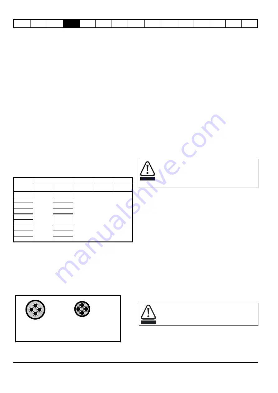
High-capacitance cables
The maximum cable length is reduced from that shown in Table 4-9 if
high capacitance motor cables are used.
Most cables have an insulating jacket between the cores and the armor
or shield; these cables have a low capacitance and are recommended.
Cables that do not have an insulating jacket tend to have high
capacitance; if a cable of this type is used, the maximum cable length is
half that quoted in the tables. (Figure 4-3 shows how to identify the two
types).
Figure 4-3 Cable construction influencing the capacitance
The cable used for Table 4-9 is shielded and contains four cores. Typical
capacitance for this type of cable is 130 pF/m (i.e. from one core to all
others and the shield connected together).
4.7.2 Motor winding voltage
The PWM output voltage can adversely affect the inter-turn insulation in
the motor. This is because of the high rate of change of voltage, in
conjunction with the impedance of the motor cable and the distributed
nature of the motor winding.
For normal operation with AC supplies up to 500 Vac and a standard
motor with a good quality insulation system, there is no need for any
special precautions. In case of doubt the motor supplier should be
consulted.
Special precautions are recommended under the following conditions,
but only if the motor cable length exceeds 10 m:
•
AC supply voltage exceeds 500 V
•
DC supply voltage exceeds 670 V
•
Operation of 400 V drive with continuous or very frequent sustained
braking
For the other cases listed, it is recommended that an inverter-rated
motor be used. This has a reinforced insulation system intended by the
manufacturer for repetitive fast-rising pulsed voltage operation.
If it is not practical to use an inverter-rated motor, an output choke
(inductor) should be used. The recommended type is a simple iron-cored
component with a reactance of about 2 %. The exact value is not critical.
This operates in conjunction with the capacitance of the motor cable to
increase the rise-time of the motor terminal voltage and prevent
excessive electrical stress.
4.7.3 Output contactor
A contactor is sometimes required to be installed between the drive and
motor for safety purposes.
The recommended motor contactor is the AC3 type.
Switching of an output contactor should only occur when the output of
the drive is disabled.
Opening or closing of the contactor with the drive enabled will lead to:
1. OI.AC trips (which cannot be reset for 10 seconds)
2. High levels of radio frequency noise emission
3. Increased contactor wear and tear
The Drive Enable terminal (T31) when opened provides a Safe Torque
Off function. This can in many cases replace output contactors.
For further information see section 4.17
4.8 Braking
The internal braking resistor can be used with the drive even though its
resistance is lower than the minimum resistance values given in
Table 4-11, because of the following reasons.
•
The braking resistor overload protection function in the drive is set
up to limit the power dissipated in the resistor.
•
The braking resistor is installed with a thermistor which will trip the
drive if the resistor is too hot.
•
The power rating of the resistor is only 50 W
If an external resistor is used with the drive, its resistance must be equal
to or greater than the value given in Table 4-11.
Model
Output cable
6kHz
8kHz
12kHz
mm
2
AWG
m
m
m
DST1201
0.75
24
50
DST1202
22
DST1203
20
DST1204
18
DST1401
24
DST1402
DST1403
22
DST1404
20
DST1405
18
Normal capacitance
Shield or armour
separated from the cores
High capacitance
Shield or armour close
to the cores
If the cable between the drive and the motor is to be
interrupted by a contactor or circuit breaker, ensure that the
drive is disabled before the contactor or circuit breaker is
opened or closed. Severe arcing may occur if this circuit is
interrupted with the motor running at high current and low
speed.
The internal braking resistor for Digitax ST is installed with a
thermistor which must be connected to the drive whenever
the internal braking resistor in installed.
WARNING
CAUTION


