21
EN
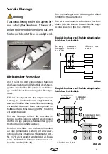
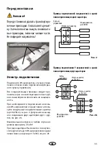
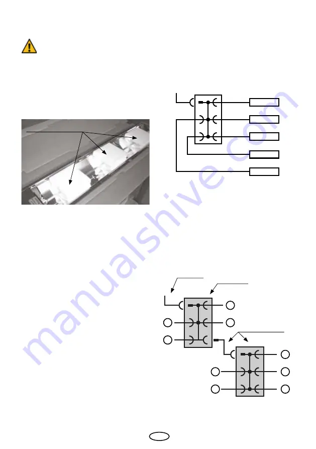
Fig. 2
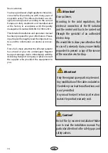
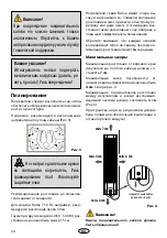
Caution!
Remove the transport stabilisers before in-
stallation. Take off the cover grill and remove
the foamed pad including all small pieces.
Make sure not to damage the emitter.
Fig. 1
Electrical connection
Before installation
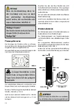
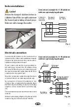
IR-radiators -
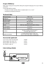
max. 3500 W
Plug adaptor,
Item 94.7811
Connection to
control unit,
Item 94.7813
Fig. 2
Fig. 2b
1
3
5
2
4
7
9
6
8
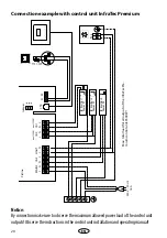
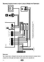
Connection example for 5 IR radiators
with one optional plug adaptor
Connection example for 9 IR radiators
with two optional plug adaptors
Connect the IR radiator to the control unit as
advised in the control unit installation manual.
Observe the instructions in the control unit in-
stallation and operation manual.
If your control unit has the corresponding ca-
ble with plug, connect the IR radiator using
this plug. Otherwise you can alternatively use
the special connection cable (item 94.7813) for
connection to the control unit.
Draw the connection cables through the ducts
or protect them in an other appropriate way.
By connection of several IR radiators to one
common line an optional plug adaptor (item
94.7812) may be used (fig. 2). Up to 2 such plug
adaptors can be connected to each other (fig.
2b).
The maximal total power load must not exceed
3500 W.
With two joined plug adaptors (fig. 2b) up to 9 IR
radiators may be connected (max. 3500 W).
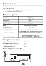
Cable
Item. 94.7813
IR plug adaptor
Item. 94.7811
Protective foam
IR plug adaptor with exten-
sion cable, item 947812
IR-radiators -
max. 3500 W
Содержание Vitae Compact
Страница 2: ...2 Deutsch 3 English 15 Русский 27 ...

