background image

22

ENVISION SERIES INSTALLATION MANUAL 

The Envision series comes with a holding charge. The charge must be adjusted in the field based on performance. 

Refrigeration piping on the split consists of installing a brazed copper line set between the blower coil unit and the unit’s split 
compressor section. To select the proper tube diameters for the installation, refer to the table on page 9. Line sets over 60 
feet long are not recommended because of oil return and pressure drop problems. The suction line must always be insu

-

lated. Handle and route the line sets carefully to avoid kinking or bending the tubes. If the line set is kinked or distorted and 
it cannot be formed back into its original shape, the bad portion of the pipe should be replaced. A restricted line set will affect 

the performance of the system.

Connection to Air Coil

Figures 1 and 2 illustrate typical Envision Split installations. The table on page 9 shows typical lineset diameters and 

maximum length. As in all R-410A equipment, a reversible liquid line filter drier is required to insure all moisture is removed 
from the system. This drier should be replaced whenever “breaking into” the system for service. All linesets should be 
insulated with a minimum of 1/2” closed cell insulation. All insulation should be painted with UV resistant paint or covering to 

insure long insulation life. 

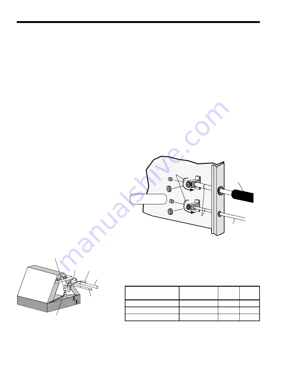
Fasten the copper line set to the blower coil unit as instructed by the coil installation instructions shown in Figure 14. 

Nitrogen should be bled through the system at 2 to 3 PSI to prevent oxidation inside the refrigerant tubing. Use a low silver 

phos-copper braze alloy on all brazed connections.

Braze line set to the service valve stubs on the 

inside front of the split cabinet as shown in Figure 

13. Nitrogen should be bled through the system at 

2 to 3 PSI to prevent oxidation contamination. Use 
a low silver phos-copper braze alloy on all brazed 
connections. Envision split units are shipped with 

a factory charge and service valves are not to be 

opened until the line set has been leak tested, 

purged and evacuated. Schrader cores should be 

removed before brazing. A heat sink should be used 

on the service valves and TXV to prevent damage 

caused by excessive heat.

Refrigeration

Replace caps after

opening system

Service ports for

attaching refrigerant

gauges

Insulated

Suction Line

Braze

Connection

Liquid

Line

ccw

ccw

Figure 13: Typical Split System Refrigerant Line Connections

Position

Description

System

Service 

Port

 CW - Full In

 Shipping Position

Closed

Open

 CCW - Full Out 1/2 turn CW

 Service Position

Open

Open

 CCW - Full Out

 Operation Position

Open

Closed

TXV ("IN" toward condensing unit)

Equalizer Bulb

Suction

Liquid

TXV has internal check valve

Figure 14: Attaching the Air Coil

Содержание NDZ 022 A11AC

Страница 1: ...uperheater Connections Electrical Startup Procedures Troubleshooting Preventive Maintenance IM1592 06 07 Envision Series Geothermal Indoor Split Heat Pumps R 410A Refrigerant 2 6 Ton Single Speed 2 6...

Страница 2: ...6 1 59 56 1 59 74 2 1 90 2 55 92 2 61 108 3 06 52 1 47 56 1 59 90 2 55 92 2 61 104 2 95 Coax and Water Piping Water Connections Size Swivel in mm 1 25 4 HWG Connection Size Swivel in mm 1 25 4 Coax Pi...

Страница 3: ...ed Loop Ground Source Systems 12 Desuperheater 13 14 Electical Data 14 Thermostat Wiring 15 Wiring Schematics 16 17 Microprocessor Control Features and Operation 18 19 Operation Logic Data 20 DIP Swit...

Страница 4: ...are located in unconditioned spaces to prevent damage from frozen water lines and excessive heat that could damage electrical components Air Coil Location Refer to the air handler manufacturer s instr...

Страница 5: ...ing an Envision Split to an air handler coil Select R 410A components only Select 12 SEER or higher air handler coil Match the air handler to the air handler coil data table on page 9 Indoor matching...

Страница 6: ...e capacity of the unit refer to page 9 Line sets should be routed as di rectly as possible avoiding unnecessary bends or turns All wall penetrations should be sealed properly Line set should not come...

Страница 7: ...oil should be located in the supply side of the furnace to avoid condensation damage to the furnace heat exchanger A high temperature limit should be installed upstream of the coil to de energize the...

Страница 8: ...swivel connector prior to attempting any connection The rubber seals are shipped attached to the waterline To make the connec tion to a ground loop system mate the brass connector supplied in CK4L con...

Страница 9: ...8 OD 3 4 OD 3 8 OD 7 8 OD 1 2 OD 74 NZ048 NAH060 3 4 OD 3 8 OD 7 8 OD 3 8 OD 7 8 OD 1 2 OD 90 NZ060 NAH060 7 8 OD 1 2 OD 7 8 OD 1 2 OD 1 1 8 OD 1 2 OD 92 NZ070 NAH060 7 8 OD 1 2 OD 7 8 OD 1 2 OD 1 1 8...

Страница 10: ...storm sewer drain field adjacent stream or pond etc Most local codes forbid the use of sanitary sewer for disposal Consult your local building and zoning depart ments to ensure compliance in your are...

Страница 11: ...iron bacteria will be pres ent a closed loop system is recommended The heat exchanger coils in ground water systems may over a period of time lose heat exchange capabilities due to a buildup of miner...

Страница 12: ...in the specification cata log Usually 2 5 to 3 GPM of flow per ton of cooling capacity is recommended in earth loop applications Multiple Units on One Flow Center When two units are connected to one l...

Страница 13: ...erheater pump to operate during these conditions actually removes heat from the DHW circulating through the unit To overcome this Envision unit microprocessors have been programmed to disengage the de...

Страница 14: ...ndicator plug 1 turn on the motor end of the pump until all air is purged from the pump then tighten the plug Use vent couplings to bleed air from the lines 6 Carefully inspect all plumbing for water...

Страница 15: ...ay Note Field installed DPST dual fuel relay Required for dual fuel installation Auxiliary Heat Relay P2 P1 Shut Down chassis Envision Split Auxiliary Heat Relay HWA Ext Total Min Max Pump Loop Unit C...

Страница 16: ...lug Ground Fuse CC CO CR1 CR2 CR3 CR4 F1 and F2 WCL HE HP LP PB1 PB2 PS RV SW1 SW2 SW3 SW4 TS Compressor Contactor Condensate overflow sensor DHW pump relay Loop pump relay Fuses Water Coil Limit Sens...

Страница 17: ...ON for unzoned Dual Cap E Series or Premier 2 speed units Thermistor Light emitting diode Green Relay coil Capacitor w bleed resistor Switch Condensate overflow Switch High pressure Switch Low pressur...

Страница 18: ...ons resume on the next compressor cycle or after 15 minutes of continuous compressor operation during the current thermostat demand cycle Hot Water Justification Since compressor hot gas temperature i...

Страница 19: ...ard Fan G only The fan starts on low speed PSC ON Regardless of fan input G from thermostat the fan will remain on low speed for 30 seconds at the end of each heating cooling or emergency heat cycle L...

Страница 20: ...ondary 1 Out On On On Off On On Emerg LED Off Off Off On Off Off Off T Stat Signal Y1 Y1 Y2 Y1 Y2 W W Y1 O Y1 Y2 O G DUAL CAPACITY UNITS Compressor Lo On Off Off Off On Off Compressor Hi Off On On Off...

Страница 21: ...play viewed at LEDs 7 Output Diagnostics Allows viewing the outputs from the control board such as the compressor reversing valve blower hot water pump and loop pump on the LED display Diagnostic Outp...

Страница 22: ...hould be painted with UV resistant paint or covering to insure long insulation life Fasten the copper line set to the blower coil unit as instructed by the coil installation instructions shown in Figu...

Страница 23: ...ling should rise and the superheat should fall until 8 16 degrees of superheat is reached when the TXV should be metering the system See operating details in the startup section of this manual for exa...

Страница 24: ...e liquid line just outside the split cabinet This location will be adequate for measurement in both modes unless a significant temperature drop in the liquid line is anticipated Measure the liquid lin...

Страница 25: ...6 128 5 586 146 5 108 35 4 228 78 1 348 106 7 468 128 8 588 146 8 110 36 4 230 78 7 350 107 2 470 129 1 590 147 1 112 37 3 232 79 2 352 107 6 472 129 4 592 147 3 114 38 2 234 79 8 354 108 0 474 129 8...

Страница 26: ...Suction Pressure PSIG Discharge Pressure PSIG Superheat Subcooling Water Temp Drop F Air Temp Rise F DB 1 5 69 81 254 334 7 13 5 13 7 10 18 24 3 0 75 87 260 340 7 14 5 13 3 6 20 26 1 5 98 113 293 373...

Страница 27: ...9 14 7 15 8 12 24 28 3 0 140 160 335 390 9 14 7 15 6 10 22 30 Second Stage Operation Suction Pressure PSIG Discharge Pressure PSIG Superheat Subcooling Water Temp Rise F Air Temp Drop F DB 1 5 120 13...

Страница 28: ...e cooling mode Cooling setpoint must be set below room temperature 3 First stage cooling will energize after a time delay 4 Be sure that the compressor and water control valve or loop pump s are activ...

Страница 29: ...ation papers Final Evaluation After the initial check of superheat subcooling values in the heating mode shut off the unit and allow it to sit 3 to 5 min utes until pressures equalize Restart the unit...

Страница 30: ...sure suction temperature here at TXV bulb in cooling modes Cooling Cycle Analysis COOLING TXV ACTIVE RIGHT TO LEFT ClgTXV Measure liquid line temperature and pressure here in both heating and cooling...

Страница 31: ...4 18 6 0 5 7 5 3 4 9 4 6 21 7 8 7 3 6 8 6 4 5 9 10 2 3 2 1 2 0 1 9 1 7 13 3 6 3 3 3 0 2 8 2 6 16 5 0 4 6 4 3 4 0 3 7 19 6 5 6 2 5 8 5 4 5 0 5 30 06 038 full load 049 part load 064 full load 072 part l...

Страница 32: ...ed and super heat and subcooling numbers calculated If superheat and subcooling are outside recommended ranges an adjustment to the refrigerant charge may be necessary Notes Refrigerant tests must be...

Страница 33: ...essary Units should never be operated without a filter Condensate Drain In areas where airborne bacteria produce a slime in the drain pan it may be necessary to treat chemically to minimize the proble...

Страница 34: ...0 UNIT DEPTH D 1 93 D 2 21 WATER IN E 6 93 E 7 21 WATER OUT F 8 44 F 9 21 BRASS SERVICE VALVE LIQUID G 11 55 G 12 14 BRASS SERVICE VALVE GAS H 13 43 H 15 83 DESUPERHEATER IN J 16 43 J 18 83 DESUPERHEA...

Страница 35: ...35 ENVISION SERIES INSTALLATION MANUAL Installation Notes...

Страница 36: ...duct research and development and reserves the right to change design and specifications without notice 2007 WFI Product Envision Series Type Geothermal Indoor Split Heat Pumps Size 2 thru 5 5 Ton Sin...

Отзывы: