


7
Operating Instructions
c
ontRoL
b
oaRD
f
unctionS
:
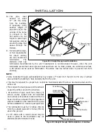
1. AUGER LIGHT:
This green light will flash in conjunction with the auger pulse.
2. MODE LIGHT:
Responsible for signaling the state of the control board. When the light is flashing the
stove is in an automatic start mode or the thermostat has control of the unit. When the light is solid,
the Heat Level Setting can be altered.
3. THERMOSTAT SWITCH:
Used to set the unit’s controls to one of three mode settings; manual,
high/low, or auto/off.
4. FEED RATE TRIM BUTTON:
Used to change the feed rate trims in ¼ second increments for all
ROOM AIR
FAN ON/OFF
ON/OFF
FEED RATE
TRIM
COMBUSTION
BLOWER TRIM
HEAT LEVEL
AUTO/OFF
HIGH/LOW
MANUAL
AUGER
C-11625
MODE
ROOM AIR
FAN ON/OFF
ON/OFF
FEED RATE
TRIM
COMBUSTION
BLOWER TRIM
HEAT LEVEL
AUTO/OFF
HIGH/LOW
MANUAL
AUGER
C-11625
MODE
1
2
3
4
5
6
8
7
9
feed settings. When this button is pressed, all the light will light up
on the Heat Output Indicator except for the one that shows the
current setting; the default setting is the number 4 light. To adjust
the setting hold the Feed Rate Trim button down and press the Heat
Level up or down buttons to adjust the setting.
5. COMBUSTION BLOWER TRIM BUTTON:
Used to change the
Combustion Blower trims in 5 volt increments for all feed settings
until it reaches line voltage. When this button is pressed, all the light
will light up on the Heat Output Indicator except for the one that
shows the current setting; the default setting is the number 2 light.
To adjust the setting hold the Combustion Blower Trim button down
and press the Heat Level up or down buttons to adjust the setting.
6. ON/OFF BUTTON:
Used to turn the unit ON and OFF.
7. ROOM AIR FAN ON/OFF BUTTON:
Used to turn convection fan
on or off.
8. HEAT LEVEL ADJUSTMENT BUTTONS:
When pressed, will
change the heat level setting of the unit up or down.
9. HEAT OUTPUT INDICATOR:
Shows the present heat output
setting.
Figure 1: Circuit Board Control
Panel Decal.
a
utomatic
S
afety
f
eatuReS
of
y
ouR
p
eLLet
S
tove
:
A. The stove will shut off when the fire goes out and the exhaust temperature drops below 120
°
F (49
°
C).
B. The stove has a high temperature safety switch. If the temperature on the hopper reaches 200
°
F
(93
°
C), the auger will automatically stop and the stove will shut down when the exhaust temperature
cools #4 light flashes. Dealer will have to reset the sensor. If this happens, call your local dealer to reset
the 200
°
F (93
°
C) high limit switch.
ALSO FIND THE REASONS WHY THE UNIT OVERHEATED.
C) The unit is equipped with a vacuum switch to monitor the venting; if it becomes blocked the vacuum
switch will turn off the auger and the #2 light on the control board will flash.
o
peRating
y
ouR
p
eLLet
S
tove
:
PRE-BURN INSTRUCTIONS
: The burn pot liner holes must be clear and the liner installed properly
against the ignitor tube for proper operation. Check the hopper for enough pellets to start the unit.
DO NOT OPERATE THE UNIT WITH THE DOOR OR ASH PAN OPEN.
Note:
The thermostat mode can be changed during normal operation.