ADVANCED FEATURES
Analog Control Mode
186 |
P a g e
Copyright © 2021 BF ENTRON and/or its affiliates. All rights reserved
Product Model:
iPAK2v2
Firmware Version:
V2.10
May 22 | Doc No 700253-2
9.8
Analog Control Mode
The iPAK2v2 supports analog control which allows the output of the inverter to be controlled via an analog input ranging
from 0 to 10 V. The control output will track the analog input, allowing the user to create dynamic current profiles.
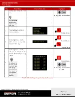
Note the following features are
not available
in Analog Control Mode:
•
Pre-heat and post heat
•
Force feedback
To use Analog Control Mode, the feature parameter must be set to
Extended
and the Weld Type parameter must be set
to
(Analog)
in the configuration settings. See the Configure the Control
section for more information.
The analog input must be wired to P4 pins 1(+) and 2(-).
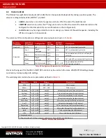
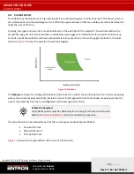
Analog Control Mode allows the user to control current in all three available modes. The current control mode must be
set on the weld program.
Main mode
0 to 10 V input signal controls
PW
0 to 100% pulse-width
CCu
0 to 100% heat (configured current)
CCC
0 to 100% calibrated current.
Table 68: Current Control Modes Available with Analog Control
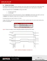
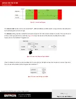
shows an example of a seam welding timing diagram using Analog Control mode.
Figure 63: Seam Welding Timing Diagram using Analog Control


