background image

OPERATION AND CARE MANUAL

Corporate Headquarters:

W164 N9221 Water Street 

 P.O. Box 443 

Menomonee Falls, Wisconsin 53052-0443 

 U.S.A.


P H O N E

:   2 6 2 . 2 5 1 . 8 3 5 6   8 0 0 . T O . B . W A R M  

U

.

S

.

A

./

CANADA


F A X

:   2 6 2 . 2 5 1 . 7 0 6 7

  w w w . e n t h e r m i c s . c o m  

8 0 0 .

8 6 2 . 9 2 7 6  

U

.

S

.

A

./

CANADA


8 0 0 . 3 2 9 . 8 7 4 4


AN ISO 13485:2003 CERTIFIED COMPANY

M N - 2 8 6 7 1   R e v   1   •   0 7 / 1 2

p r i n t e d


i n


u

.

s

.

a

.

Fluid

Warming

Cabinet

EC230L
EC340L
EC390L
EC770L


230V

EC230L

EC340L

EC770L

EC390L

Содержание EC230L

Страница 1: ...O N E 2 6 2 2 5 1 8 3 5 6 8 0 0 T O B W A R M U S A CANADA F A X 2 6 2 2 5 1 7 0 6 7 w w w e n t h e r m i c s c o m 8 0 0 8 6 2 9 2 7 6 U S A CANADA 8 0 0 3 2 9 8 7 4 4 AN ISO 13485 2003 CERTIFIED COMPANY MN 28671 Rev 1 07 12 p r i n t e d i n u s a Fluid Warming Cabinet EC230L EC340L EC390L EC770L 230V EC230L EC340L EC770L EC390L ...

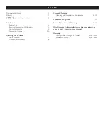
Страница 2: ...nsion Drawings 5 6 Operating Instructions Control Features 7 Operational Procedures 8 Care and Cleaning Cleaning and Preventative Maintenance 9 10 Troubleshooting Guide 11 Service Parts Lists and Drawings 12 16 Wire Diagrams Always refer to wire diagram under top cover of unit for most current version Warranty Transportation Damage and Claims Back Cover Limited Warranty Back Cover ...

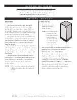
Страница 3: ...d to the factory as soon as possible to assure prompt service in the event of a warranty parts and labor claim This manual must be read and understood by all people using or installing the equipment model Contact the service department if you have any questions concerning installation operation or maintenance NOTE All claims for warranty must include the full model number and serial number of the ...

Страница 4: ...installation operation or maintenance information that is important but not hazard related 1 This fluid warming cabinet is intended for warming injection and or irrigation fluids ONLY No other use for this device is authorized or recommended 2 This device is intended for use in commercial establishments where all operators are familiar with the purpose limitations and associated hazards of this de...

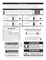
Страница 5: ...S VOLTAGE IDENTIFIED ON APPLIANCE RATING TAG Wire diagram located under top cover of unit To prevent an electrical shock hazard between the appliance and other appliances or metal parts in close vicinity an equalization bonding stud is provided An equalization bonding lead must be connected to this stud and the other appliances metal parts to provide sufficient protection against potential differe...

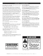
Страница 6: ... fluids IRR or injection fluids INJ with separate temperature ranges provided depending on the choice selected IRR temperature range 37 to 66 C 98 to 150 F INJ temperature range 37 to 40 C 98 to 104 F A fan located inside the chamber mixes the air to prevent temperature stratification and to ensure an accurate chamber temperature for each mode Within 0 1 67 C 0 3ºF for set points of 43 to 66 C 110...

Страница 7: ...NECTION 21 50 546 7mm CAVITY 28 0 710 7mm 17 50 445 3mm 11 89 301 9mm 40 91 1039 0mm 17 85 453 4mm 9 189 233 4mm 11 50 292 1mm 8 07 204 5mm ELECTRICAL CORD LENGTH est 8 2 438mm 33 4 849 2mm 26 96 684 6mm 20 0 508 0mm CAVITY HEIGHT 14 13 358 7mm CAVITY WIDTH 21 63 549 3mm CAVITY DEPTH 1 462 36 9mm CORD 43 38 1101 8mm OVERALL HANDLE TIP 28 53 724 5mm 24 13 612 7mm 8 70 220 8mm 17 37 441 1mm 20 67 52...

Страница 8: ...NDLE 0 53 13 6mm 19 42 493 2mm 25 46 646 7mm CAVITY 17 34 440 3mm CAVITY 18 84 478 6mm WITH FEET 17 93 455 5mm 0 45 11 5mm 12 45 316 3mm CAVITY CORD LENGTH est 8 2 438mm E C 7 7 0 L D I M E N S I O N S 11 00 280 3mm 52 80 1341 0mm 35 00 889 5mm 28 00 730 8mm 11 00 280 3mm 2 20 55 6mm OFF ON 30 10 764 2mm 25 10 637 7mm 5 500 140 4mm 18 90 480 3mm Cavity 25 20 639 2mm 26 90 683 5mm Cavity 35 10 892m...

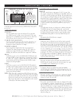
Страница 9: ...he ON OFF key to reset the control Inspection of the product in the cavity may be necessary ERROR This illuminates when an over temperature condition is detected The ERROR indicator will remain illuminated even after the over temperature condition is cleared until the warmer is turned off This will alert the operator that the control has indicated an OVERTEMP and the product in the cavity should b...

Страница 10: ...40 C 98 to 104 F NOTE The warmer is designed to warm fluids to the appropriate temperature recommended by your supplier The warm up stabilization time will vary depending on the warmer load Exercise judgment to determine inventory rotation protocols and warm up time for the fluids you use Caution Check fluid temperature prior to use Verify that the fan at the back or top of the chamber is rotating...

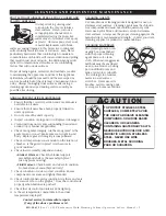
Страница 11: ...loth When more aggressive methods must be employed use a non abrasive scouring pad on difficult areas and make certain to scrub with the visible grain of surface metal to avoid surface scratches Never use wire brushes metal scouring pads or scrapers to remove residue ANNUAL PREVENTATIVE MAINTENANCE 1 Ensure that the correct Operation and Care Manual is available to all users 2 Ensure that all user...

Страница 12: ...rinsing This solution must be approved for use on stainless steel surfaces Replace support assembly 5 Clean the exterior of the cabinet with a cleaner recommended for stainless steel surfaces Spray the cleaner on a clean cloth and wipe with the grain of the stainless steel 6 Clean the window glass with a standard commercial glass cleaner 7 Wipe control panel door vents door handles and door gasket...

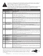
Страница 13: ...cuit breaker switch turned ON for at least 24 hours after resetting Upon resolving an E 60 error check that the date and time are correct E 61 Real Time Clock Error Call Service E 80 EEPROM Error Ensure that all temperature and times are properly set If error continues call Service E 81 EEPROM Error Call Service E 82 EEPROM Error Call Service E 83 EEPROM Error Call Service E 87 EEPROM Error Stored...

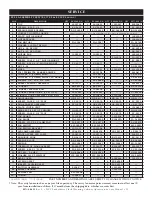
Страница 14: ...2206 1 5014019 21 BASKET 1 BS 28518 2 BS 28517 3 BS 28516 22 BASKET SUPPORT RAIL 2 1002305 4 1002302 6 1002304 23 BASKET SLIDE GUIDE 1 SET OF 2 1 GI 25941 2 GI 25941 3 GI 25942 24 WINDOW DOOR ASSEMBLY right hinge 1 5009043 1 5010808 1 5010908 1 5001253 25 DOOR HANDLE 1 HD 24171 1 HD 24171 1 HD 24171 1 HD 24171 26 SCREW 10 32 X 1 2 FLAT 4 SC 2073 4 SC 2073 4 SC 2073 4 SC 2073 27 DOOR GASKET ASSEMBL...

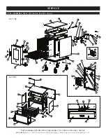
Страница 15: ...S ARE SUBJECT TO CHANGE WITHOUT NOTICE FULL ASSEMBLY VIEW EC770L EC390L shown 2 1 3 4 5 6 7 8 9 2 10 9 8 11 12 13 8 14 15 16 2 17 18 19 20 21 22 23 24 25 26 27 2 28 29 30 31 32 33 34 2 35 36 38 37 2 39 40 41 42 43 44 2 25 24 27 29 15 15 1 3 4 31 45 45 46 32 39 40 36 31 EC770L EC390L 20 47 7 13 EC230L EC340L 48 ...

Страница 16: ...19 1 BK 3019 9 CIRCUIT BREAKER SWITCH 1 SW 33826 1 SW 33826 1 SW 33826 1 SW 33826 10 TERMINAL BLOCK PORCELAIN 1 BK 33546 1 BK 33546 1 BK 33546 1 BK 33546 11 SCREW M4 X 0 7 X 6MM PAN 2 SC 22271 2 SC 22271 2 SC 22271 2 SC 22271 12 COVER HI LIMIT 1 1009751 1 1009751 1 1009751 1 1009751 13 THERMOSTAT MANUAL RESET 1 E3030TT 1 E3030TT 1 E3030TT 1 E3030TT 14 GROUND SCREW 1 SC 2190 1 SC 2190 1 SC 2190 1 S...

Страница 17: ...R V I C E PART NUMBERS AND DRAWINGS ARE SUBJECT TO CHANGE WITHOUT NOTICE 18 19 20 13 14 15 16 17 12 11 10 9 8 7 6 5 4 3 2 1 EC770L EC390L ELECTRICAL VIEW EC770L EC390L shown 19 20 21 3 21 17 9 8 23 14 13 6 4 10 24 24 26 27 22 located under the bonnet located under the bonnet 24 22 18 ...

Страница 18: ... 3226 RING CONNECTOR 6 8 6 12 BU 3105 SHOULDER BUSHING 6 8 6 12 ST 2439 STUD 10 32 6 8 6 12 NOT SHOWN OPTIONS AND ACCESSORIES QTY EC230L P N QTY EC340L P N QTY EC390L P N QTY EC770L P N CART WITH CASTERS CONTACT FACTORY CONTACT FACTORY N A N A CASTERS 3 76mm Platform E5089 must be ordered as a base when ordering casters or legs for this unit 1 SET 5012693 N A N A N A CASTERS 5 127mm Platform E5089...

Страница 19: ...MN 28671 Rev 2 230V Enthermics Fluid Warming Cabinet Operation Care Manual 17 REFER TO WIRE DIAGRAM UNDER TOP COVER FOR MOST CURRENT VERSION ...

Страница 20: ...MN 28671 Rev 2 230V Enthermics Fluid Warming Cabinet Operation Care Manual 18 REFER TO WIRE DIAGRAM UNDER TOP COVER FOR MOST CURRENT VERSION ...

Страница 21: ...MN 28671 Rev 2 230V Enthermics Fluid Warming Cabinet Operation Care Manual 19 REFER TO WIRE DIAGRAM UNDER TOP COVER FOR MOST CURRENT VERSION ...

Страница 22: ...MN 28671 Rev 2 230V Enthermics Fluid Warming Cabinet Operation Care Manual 20 REFER TO WIRE DIAGRAM UNDER TOP COVER FOR MOST CURRENT VERSION ...

Страница 23: ...irst This warranty does not apply to 1 Calibration 2 Equipment damage caused by accident shipping improper installation or alteration 3 Equipment used under conditions of abuse misuse carelessness or abnormal conditions including equipment subjected to harsh or inappropriate chemicals including but not limited to compounds containing chloride or quaternary salts poor water quality or equipment wit...

Отзывы: