


Installation and Operation Manual - DustEx
Service and Maintenance
Doc.-ID: COM_OXI_Dust_11022020
11
5.8
Exchange of Probe Inner Parts
Switch off the electronic unit, take the probe out of the protection tube and wait until it has cooled down.
Warning hot surface
The probe may only be removed with heat-insulated gloves. Before removing the probe, always switch off
the supply voltage to the electronic system. After removal, store the probe in a safe, protected place and
wait until it has cooled down below 35°C/95°F.
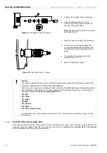
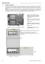
Disconnect the wires of the probe
inner part
, the two tubes
-
and the thin reference air tube.
Loosen the two screws
and
dismount the plate
. Now the
complete probe inner part (4 hole
ceramic rod with measuring signal
wire, thermocouple and heater)
can be removed carefully
.
Figure 34
- Probe connection box
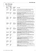
Insert the new inner part carefully into the probe and screw in the plate (take care that the new inner part moves
freely within the probe). The probe inner part is now being pushed against the sensor by the spring. Reconnect all
electrical and pneumatic connections. Connect the wires as follows.
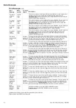
Terminal
Color
Description
Polarity
Unit
white /brown
signal wire, measuring cell
-
mV
brown
signal wire, measuring cell
+
mV
green
thermocouple element 1
+
mV
white
thermocouple element 1
-
mV
green
thermocouple element 2
+
mV
white
thermocouple element 2
-
mV
black
heating element
blue
heating element
green/yellow ground/earth
heater
grey
solenoid valve (remains attached)
grey
solenoid valve (remains attached)
white/red 1
COe Sensor
mV
white/red 2
COe Sensor
mV
red
COe Sensor heater
mV
red
COe Sensor heater
mV
Connection of the probe inner part
Install the probe; wait for the system to reach its operating temperature. Carry out an two point calibration after
24 hours of operation.