

Seite
3
von
6
4.
Requirements
stable and correctly configured network environment (with a DHCP server/router)
CAT5 (or higher) network cable for connecting the gateway to a network
Latest generation web browser to access the gateway's web interface (Google Chrome, Mozilla Firefox
with Javascript enabled)
Sensors and actuators should be within 20 meters of buildings and 40 meters of the gateway. These
distances may vary depending on the structure of the building and the number of radio transmission
devices.
5.
Outlets
LAN [RJ45] with activity and connection speed LEDs, USB [1x]
Antenna connection [ANT], power supply [5V DC], reset, power LED
6.
Mounting
When selecting a suitable location for mounting the device, make sure not to drill near electrical
switches, sockets or cables.
6.1.
Wall mounting
The holes in the housing can be used to fix the device to a wall.
6.2.
Rail Mounting
Attach the DIN rail mounting clip to the back of the gateway with the supplied screw [D].
6.3.
Positioning variant
Remove the covers from the supplied self-adhesive feet [D] and attach them to the corners of the bottom of
the Gateway.
7.
Hardware installation
Screw the antenna or antenna cable onto the antenna connector of the gateway.
Connect the gateway directly to a router using the network cable [E] at a network outlet.
Connect the supplied power supply [C] to the gateway and plug it into a power outlet..
WARNING: 230 V mains voltage. Avoid physical contact! Danger to life!
8.
Commissioning
8.1.
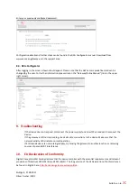
Device detection and access
To access the device, it must first be found in the network. As soon as the IP address of the gateway is known, a
computer in the same network can be accessed via the web interface.


