


6
Installation Diagrams and Thermostat Wiring
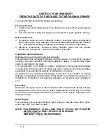
This appliance requires a masonry or pre-manufactured chimney listed to UL103HT, sized
correctly.
Figure 2 – Installation into a HT Pipe Flue System.
LEFT
– Through the Roof
RIGHT
– Through the Wall
Figure 1 – Installation into a Masonry Flue
Figure 3 – Hot air outlet hook-up to ductwork.
NOTE:
Be sure to connect to ductwork from
furnace’s 8”
hot air outlet
only (see Section V)
.
Air Flow
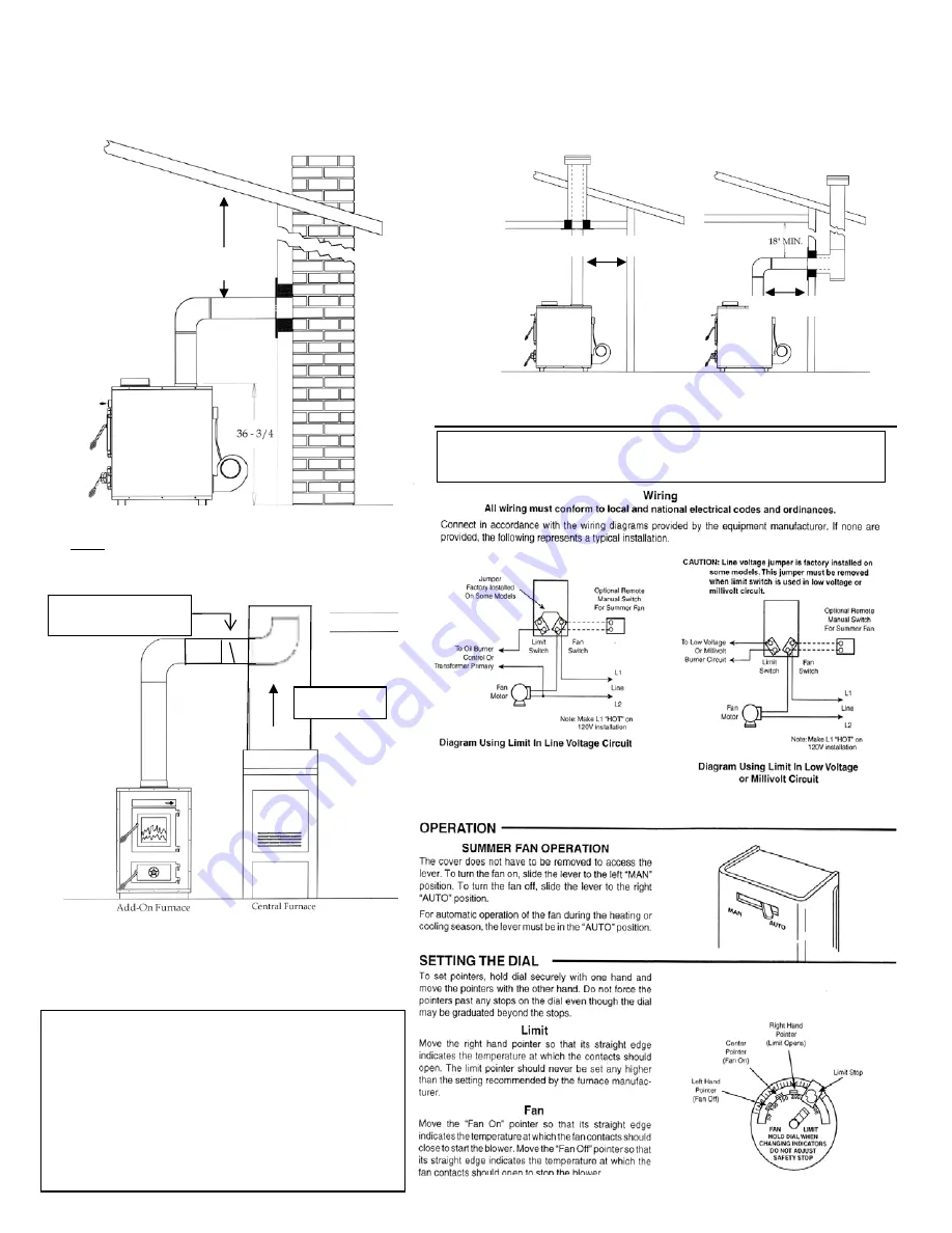
Figure 4 – Blower thermostat wiring diagram.
IMPORTANT NOTE:
Do NOT connect this furnace to
an
external
thermostat.
18” Min.
18” Min.
NOTE: 13” required from back of unit to a combustible.
16” required from sides of unit to a combustible.
See Floor and Wall Protection sections and data label
on stove for all clearances.
18” Min.
Recommended position
of Backflow Damper
To prevent air flow from central furnace
being directed back into the Add-on furnace:
A Backflow Damper is required in the 8” hot air
outlet pipe that connects from the Add-On
Furnace to the Central Furnace (see Figure 3).
We also recommend a 8” (eight inch), 90
degree elbow (a slightly larger hole will be
required for installation) inside central furnace
plenum or ductwork.


