
001-01-000083 Rev. 001
Page 3 of 5
mounted racks. Be sure to use the hole symbol
Ⓑ
.
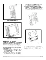
Drill six (6)
3/16” pilot holes. These holes mate with
the mounting brackets located at the rear corners of
the frame. The frame will be fastened with two screws
in each of the upper brackets and one screw in each
of the lower brackets, as shown in Figure 6.
f
Before attempting to fasten the mounting frame to the
wall, insert a screw into the top pilot hole on either the
left or right side. Partially thread the screw into the
hole, leaving the screw head approximately 1/4
” from
the surface.
g
Hold the mounting frame against the wall while resting
the cutout of the bracket on the installed screw. Align
the other five mounting holes and install a screw in
each hole. Tighten all six (6) screws securely.
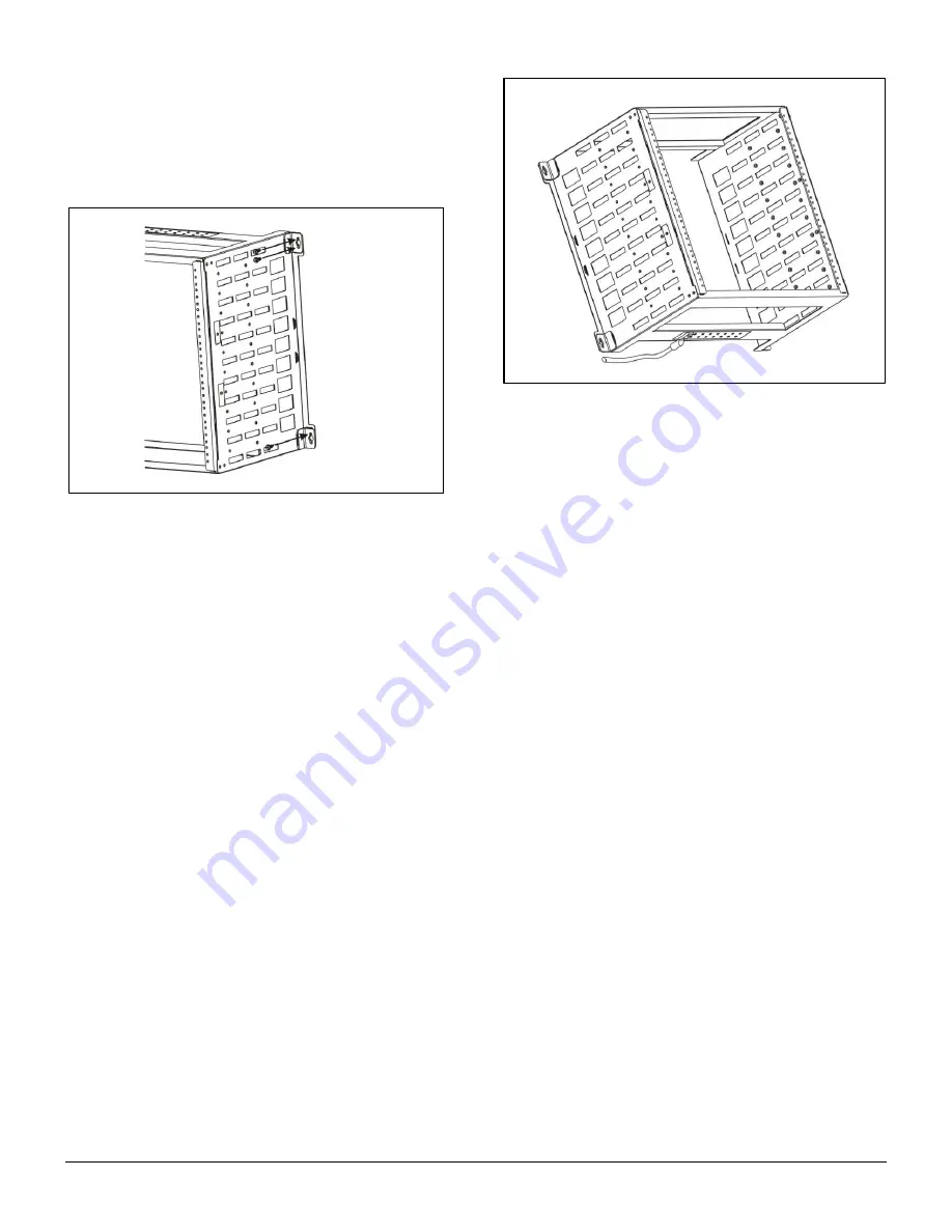
B. Frame grounding
c
Locate the eight (8) pairs of pre-installed grounding
screws with lock washers on the crossbar of the
frame. The grounding screws are 10-32 x
3/8” on 5/8”
centers.
d
Install a dual ground lug (customer provided) with
holes on 5/8” centers
beneath the included screws
and washers on one pair of grounding holes. Tighten
the screws to fasten the lug to the mounting frame.
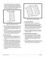
The example in Figure 7 illustrates the frame
positioned with grounding screws facing downward.
e
Connect a ground wire of appropriate gauge to the
ground lug and attach the other end of the wire to a
bonded ground point, per local procedures for network
equipment.
Figure 7. Frame grounding example
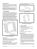
C. Equipment Installation
c
Install rack equipment with 19” hole spacing b
y
carefully sliding the chassis through the front of the
WR-10U and aligning chassis mounting ears with the
threaded holes in the rails of the WR-10U frame.
Insert and tighten #12-24 machine screws (customer
provided) on each side of the chassis. An example of
a fully populated wall rack is shown in Figure 2.
d
Attach ground lugs associated with each equipment
chassis to the threaded ground holes on the WR-10U
crossbar as needed.
D. Optional Cable Guide Installation
c
To install a cable guide to the side of the mounting,
first remove the sliding cover from the cable guide.
Insert two of the #10-
32 x 3/8” screws
(included in
CG-5 package) through the cable guide and into the
threaded holes on the side of the WR-10U frame
(Figure 8).
d
Groom cabling from the front of the chassis to the wall
through the cable guide on the side of the WR-10U, as
shown in Figure 9, and replace the sliding cover.
Figure 6. Mounting screw locations
Figure 7. Mounting screw locations


