EngA Engineered Air XES-SC Series Скачать руководство пользователя страница 19

A   

XES SC MANUAL 


IOM-58 

19 of 30 

June 14 R5 

All wiring shall be installed according to the requirements of the authorities having jurisdiction. Field 
wiring, internal wiring diagrams and unit operating functions are included in the control cabinet of the 
unit. The power requirements are indicated on the rating plate. 

SPLIT UNIT WIRING 

 
All split wiring must be completed by an electrician prior to starting the equipment.    A number of 
different methods are used to reconnect the wiring. 
 
Power wire:  this wiring is generally not broken or spliced, and will extend from the device back to the 
contactor or terminal block inside the electrical panel(s).  The wire will be tagged to identify which panel it 
extends to and will be numbered to the corresponding connection. 
 
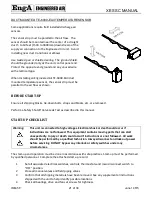
The location of the equipment split line may result in the wire being disconnected at the device it is 
feeding.  The wire bundle will be tagged and identified.  Confirm correct rotation of 3 phase devices after 
the wiring connections has been completed. 
 
Control wire:  this wire is typically broken near the split line, to be reconnected at either a enclosed 
terminal block, junction box or extended to a nearby control panel.  Each wire or wire bundle will be 
tagged and numbered to indicate the location it is sent to. 
 
Sensor wire shield:  The drain wire from the shield must be grounded (at one end only).  A ground 
connection point is available for connection at the point of termination. 
 
All loose wiring must be securely fastened to the equipment casing upon completion. 
 

Caution:


Temporary Power Generation 
 
The warranty will be void if the voltage being fed from any temporary generator is not 
within 10% of the nominal rated nameplate voltage and voltage imbalance shall be 
limited to 2%.  A power monitor shall be installed by others to properly monitor power 
quality and conditions. 
 
All generator sets shall be provided with overcurrent and earth-fault protection. The 
protective apparatus should be capable of interrupting, without damage, any short-
circuit current that may occur.


Warning:


No unspecified external load shall be added to the control transformer circuit(s) or to 
the main power circuit(s). 


Содержание Engineered Air XES-SC Series

Страница 1: ...FACTORY USA HEAD OFFICE AND FACTORY CANADIAN FACTORY 1401 HASTINGS CRES SE CALGARY ALBERTA T2G 4C8 Ph 403 287 4774 Fx 888 364 2727 32050 W 83 rd STREET DESOTO KANSAS 66018 Ph 913 583 3181 Fx 913 583 1...

Страница 2: ...rical Installation 18 Split Unit Wiring 19 Recommended 24v Field Wiring Size 20 Duct Mounted Te 6000 Ea3 Temperature Sensor 21 Before Start Up 21 Start Up Check List 21 Operation 23 Combustion And Fin...

Страница 3: ...to the national service manager SAFETY PRECAUTIONS Read understand and follow the complete manual before beginning the installation including all safety precautions and warnings WARNING FIRE OR EXPLOS...

Страница 4: ...enting a possible threat of flue gas spillage into the building Warning This unit is connected to high voltages Electrical shock or death could occur if instructions are not followed This equipment co...

Страница 5: ...arranties express or implied ENGINEERED AIR specifically disclaims any implied warranty of merchantability and or fitness for purpose Under no circumstances shall ENGINEERED AIR be liable to nor be re...

Страница 6: ...e may be internal damage Remove protective covers and check for internal damage Replace covers if the unit is not being assembled or installed at this time Open access doors and check for internal dam...

Страница 7: ...th the local authorities having jurisdiction 3 The installation of this unit shall be in accordance with the latest edition of the Canadian Natural Gas and Propane Installation Code C S A Standard B14...

Страница 8: ...cordance with all other National State and Local Codes and in accordance with the local authorities having jurisdiction MINIMUM CLEARANCE FOR SERVICE AND TO COMBUSTIBLES For Safety and Service the fol...

Страница 9: ...ly slide the heat section forward until the back and sides of the heat and fan section are flush This will lock the two pieces together at the back as the locking clip engages Do not damage foam tape...

Страница 10: ...e motor and upper limit control wires to the limit as shown on wiring diagram g Install the inner fan door h Connect the vent pipe between the heat section and the top collar of the fan section The ve...

Страница 11: ...ibes two options for separated combustion systems Side Wall Vent o EngA Supplied o By Others Vertical Vent COMBUSTION AIR DUCT Each separated combustion XES heater shall be equipped with its own combu...

Страница 12: ...enting Any run of single wall vent pipe passing through an unheated space should be insulated with insulation rated for at least 550 F 280 C to prevent condensing In cases where condensing is expected...

Страница 13: ...A XES SC MANUAL IOM 58 13 of 30 June 14 R5 Figure 2 Separated Approved Vents By Others...

Страница 14: ...A XES SC MANUAL IOM 58 14 of 30 June 14 R5 Side Wall Vent Engineered Air Engineered Air supplied through wall concentric vent terminations are recommended and approved for use with XES furnace models...

Страница 15: ...A XES SC MANUAL IOM 58 15 of 30 June 14 R5...

Страница 16: ...Where the Engineered Air supplied concentric flue termination cannot be used separate approved wall terminations may be supplied and used by the installing customer Installation of the fresh air inta...

Страница 17: ...An approved vent cap eg Breidert furnished by the customer must be installed at the termination point of the vertical vent system The vent in this arrangement is category 1 B Vent is acceptable Instal...

Страница 18: ...dividual shutoff valve must be disconnected from the gas supply piping system during any testing of that system at test pressures in excess of 0 5 psi 3 5 kPa The appliance must be isolated from the g...

Страница 19: ...ring connections has been completed Control wire this wire is typically broken near the split line to be reconnected at either a enclosed terminal block junction box or extended to a nearby control pa...

Страница 20: ...a particular control circuit the field wiring is connected to Refer to the internal wiring diagram of the unit 2 The table above is based on a maximum 10 voltage drop on a 24V control circuit Wire siz...

Страница 21: ...Safety Shutoff Valve Leak Test as described in this manual START UP CHECK LIST Warning This unit is connected to high voltages Electrical shock or death could occur if instructions are not followed Th...

Страница 22: ...2 and therefore is OK If voltage imbalance is greater than two percent 2 turn off main disconnect and contact the installing electrical contractor to have the voltage condition corrected 10 Purge all...

Страница 23: ...trols are properly located and correctly field wired Some equipment may contain programmable unitary controllers or programmable logic controllers PLC Additional information can be obtained from the s...

Страница 24: ...l controls Recheck setting of all limits and temperature controls UNIT SHUT DOWN INSTRUCTIONS Service Shut Down 1 Set the thermostat in the OFF position 2 Close the manual firing valve in the manifold...

Страница 25: ...mponents Wiring errors can cause improper and dangerous operation Verify proper operation after servicing Warning Any replacement part must be of equivalent listing or certification and be functionall...

Страница 26: ...the pulleys the V belt does not have to be extremely tight It should be as loose as possible without slipping in the pulley grooves Belt deflection 3 4 19mm for each foot 300mm of span between the pul...

Страница 27: ...equent changes may be required during the economizer season Units that operate with high levels of outside air should have filters removed or moved to winter filter location if available during the wi...

Страница 28: ...toff valve 4 Immerse the opposite end of the 6mm tube cut to a 45 angle vertically 13mm into a clear container of water 5 Count the number of bubbles appearing during a 10 second period 6 If the bubbl...

Страница 29: ...n of all burners Tighten or replace blower belt Check I D fan and switch Clean or replace filters Symptom No Heat POSSIBLE CAUSE PROBLEM REMEDIES Blown control module fuse Thermostat calling ventor mo...

Страница 30: ...Rotation correct Amperage measurement A Gas line supply pressure Off w c High fire w c Manifold gas pressure at high fire w c All field wiring is complete and installed as per the wiring diagram All c...

Отзывы: