


Page 1
INSTALLATION, OPERATION
AND MAINTENANCE MANUAL
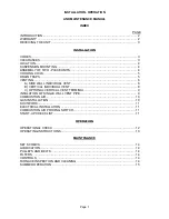
INDEX
PAGE
INTRODUCTION ............................................................................................................. 2
WARRANTY ................................................................................................................... 2
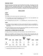
RECEIVING THE UNIT ................................................................................................... 3
INSTALLATION
CODES ........................................................................................................................... 3
CLEARANCES ................................................................................................................ 3
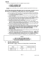
LOCATION...................................................................................................................... 4
SUSPENSION MOUNTING ............................................................................................. 4
ASSEMBLY OF TWO - PIECE UNITS............................................................................. 4
COOLING COILS ............................................................................................................ 5
DRAIN TRAPS ................................................................................................................ 5
VENTING ........................................................................................................................ 6
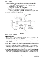
A) SIDE WALL INDIVIDUAL VENT ............................................................................ 6
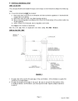
B) VERTICAL INDIVIDUAL VENT.............................................................................. 8
C) OPTIONAL VERTICAL VENT TERMINAL ............................................................. 9
INSULATION OF SINGLE WALL VENT PIPE.................................................................. 9
COMBUSTION AIR ....................................................................................................... 10
GAS INSTALLATION .................................................................................................... 10
DUCTWORK................................................................................................................. 11
ELECTRICAL INSTALLATION ...................................................................................... 11
COMBUSTION AIR PROVING SWITCH........................................................................ 11
START-UP CHECK LIST............................................................................................... 11
OPERATION
OPERATIONAL CHECK ............................................................................................... 12
OPERATING INSTRUCTIONS ...................................................................................... 13
MAINTENANCE
SET SCREWS .............................................................................................................. 14
LUBRICATION .............................................................................................................. 14
PULLEYS AND BELTS ................................................................................................. 14
FILTERS ....................................................................................................................... 14
CONTROLS .................................................................................................................. 14
FURNACE INSPECTION AND CLEANING .................................................................... 14
SUMMER OPERATION ................................................................................................ 15