background image

A


CRD-200


9 of 14 


Sep 06 

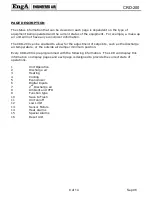
PAGE 1 – UNIT OPERATION 


E n  g A       F A  N   D E L A Y   O N  

< # 0  1        H T  G   M O D E         > 

 
-Describes the current operating mode and fan status, as well as the program number. 


PAGE 2 – DISCHARGE AIR 


2         D I S   A I R =


  6 5 

F    

<   A D J   S E T   P T =  7 0          > 

 
-Notes the discharge air temperature and setpoint.  Multizone equipment will indicate the hot 

deck temperature.  Dehumidification equipment will refer to the final reheat temperature. 
-Setpoint changes can be made here, but will not be saved unless saved to flash memory. 


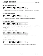
PAGE 3 - HEATING 


3           H T G =    8 7 %    


<       M A I N   H E A T   O N       > 

 
-Shows the actual heating signal output (%) from the C-TRAC3 to the heating device. 
-Indicates the return signal to confirm heating is operational. 


PAGE 4 - COOLING 


4            C L G =    3 3 %     


<          C Y C L I N G    O N          > 

 
-Describes the number of cooling stages as a percentage.  For example, if the equipment has 
3 compressors the output will indicate 33, 66 and 100%. 

-Also indicates any control corrections in progress. 


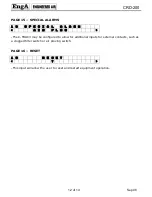
PAGE 5 - ECONOMIZER 


5           E C O N =    7 0  %  


<   A D J   M I N   P O S =    1  0  %   > 


-Indicates the actual C-TRAC3 economizer output and the minimum outside air setpoint (%). 
-Setpoint changes can be made here, but will not be saved unless saved to flash memory 
(page 10). 

-Deviations may occur between setpoint and actual output.  Refer to the  
C-TRAC3 manual for clarification. 
 

Содержание CRD-200 C-TRAC3

Страница 1: ...NADIAN EASTERN FACTORY 1401 HASTINGS CRES SE CALGARY ALBERTA T2G 4C8 Ph 403 287 4774 Fx 888 364 2727 32050 W 83rd STREET DESOTO KANSAS 66018 Ph 913 583 3181 Fx 913 583 1406 1175 TWINNEY DRIVE NEWMARKE...

Страница 2: ...rther information is required please contact the nearest Engineered Air office Under no conditions except for temporary copying should the unit function be removed from the unit There are two copies p...

Страница 3: ...ration 9 Page 2 Discharge Air 9 Page 3 Heating 9 Page 4 Cooling 9 Page 5 Economizer 9 Page 6 Digital Inputs 10 Page 7 2nd Discharge Air 10 Page 8 Ambient And Vfd 10 Page 9 Function Type 10 Page 10 Sav...

Страница 4: ...A CRD 200 4 of 14 Sep 06 DEL ESC ENTER g M a e l i s MOD...

Страница 5: ...anel can be ordered with the following options Option 1 Display only Option 2 Unit on off switch Option 3 Unit on off auto switch c w internal time clock Option 4 Unit occupied unoccupied off switch c...

Страница 6: ...t Press and then press to decrease and to increase the value When the appropriate value has been set press to save To ensure the value is not lost in the event of a power failure or equipment servicin...

Страница 7: ...COMPLY WITH THE CANADIAN ELECTRICAL CODE 2 ALL WIRING SHOWN SHALL BE COMPLETED BY INSTALLER 1 FIELD WIRING VOLTAGE DROP NOT TO EXCEED 8 7 6 24VAC 24VAC 24VAC B A C 2 1 4 3 6 5 8 7 RJ45 2 1 4 3 6 5 8...

Страница 8: ...tpoints such as the discharge air temperature or the outside air damper minimum position Every CRD 200 is preprogrammed with the following information The LCD will display this information on display...

Страница 9: ...A I N H E A T O N Shows the actual heating signal output from the C TRAC3 to the heating device Indicates the return signal to confirm heating is operational PAGE 4 COOLING 4 C L G 3 3 C Y C L I N G...

Страница 10: ...modulate 1 Heating is allowed HS 0 Heating is disabled 1 Occupied mode FS 0 Unit off 1 Unoccupied mode K 0 Unit off PAGE 7 2ND DISCHARGE AIR 7 C O L D D E C K 6 5 o F A D J S E T P T 5 0 This sensor...

Страница 11: ...L O W L I M I T O K S E T P T 4 0 o F The low limit or freeze protection setpoint is preprogrammed and cannot be changed from the CRD 200 This page indicates the low limit setpoint and alarm indicati...

Страница 12: ...L A L A R M A I R F L O W The C TRAC3 may be configured to allow for additional inputs for external contacts such as a clogged filter switch or air proving switch PAGE 16 RESET 1 6 R E S E T This inp...

Страница 13: ...it Operation NO MODE DIS AIR F HOT DECK F SET PT Page 2 Discharge Air ADJ SET PT NO HTG HTG Page 3 Heating MAIN HEAT ON NO CLG CLG CYCLING ON Page 4 Cooling CYCLING OFF NO ECON ECON V MIN POS Page 5 E...

Страница 14: ...e 9 Function DEHUMID Page 10 Save Setpoints YES On Page 11 Unit On Off Off LOW LIMIT OK LOW LIMIT ALARM Page 12 Low Limit SET POINT F TEMP SENSORS OK DIS FAILED AMB FAILED Page 13 Sensor Failure SEC F...

Отзывы: