ENERVEX BEF 225x Скачать руководство пользователя страница 3

3

010.1220.0719 01.21

1. GENERAL INFORMATION

  1.1 Introduction ......................................................4
  1.3 Components ....................................................4
  1.4 Shipping ...........................................................5
  1.5 Accessories ......................................................5
  1.6 Listings .............................................................5
  1.7 Warranty ...........................................................5

2. SPECIFICATIONS AND DIMENSIONS

  2.1 Specifications ...................................................6

3. MECHANICAL INSTALLATION

  3.1 Positioning ........................................................7
  3.2 Door Position ....................................................8
  3.3  Floor Or Roof Mounting ....................................9
  3.4 Ceiling Mounting ...............................................9
  3.5 Connection to Duct ...........................................10  

  3.6 Connection to Flexible Duct ..............................10
  3.7  Outdoor Termination .........................................10
  3.8  Field Junction Box ............................................11

4. ELECTRICAL INSTALLATION

  4.1 General .............................................................12
  4.2  Motor Controller ...............................................12
  4.3 Mounting of EDrive Motor Controller .................13
  4.4 Grounding Guidelines ........................................13
  4.5  EMC Filter Disconnect ......................................13
  4.6  Electrical Connection of the Motor and EDrive ..14
  4.7  Motor Terminal Connections .............................14
  4.8 Wiring Diagram BEF 225-355x / 1x120V ...........14
  4.9  Wiring Diagram BEF 225-800x / 3x208-480V ...15
  4.10 Checking and Changing Rotation of Impeller ...15
  4.11 Installing a Proven Flow System ......................16

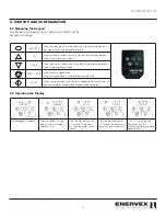
5. STARTUP AND CONFIGURATION

  5.1 Managing the Keypad .......................................17
  5.2 Operating the Display ........................................17
  5.3 Changing Parameters .......................................18
  5.4 Read Only Parameter Access ...........................18
  5.5  Resetting Parameters .......................................18
  5.6  Resetting a Fault ..............................................18
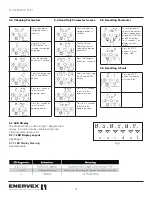
  5.7  LED Display ......................................................18
  5.8  Start Up Sequence (Auto Tune) ........................19

6. MAINTENANCE AND TROUBLESHOOTING

  6.1 Cleaning Intervals ..............................................20
  6.2 Cleaning ...........................................................20
  6.3 Service..............................................................20
  6.4 Replacement Parts Ordering .............................21

7. WARRANTY TERMS ......................................22

Content

WARNING

This product is equipped with an electronically 

commutated (EC-motor) and can not be 

connected directly to ac mains. Motor must 

be connected to approved motor controller 

to ensure proper function. Failure to use approved motor 

controller may result in damage to the motor.

ATTENTION

Ce produit est équipé d’un commutateur électronique 

(moteur EC) et ne peut pas être connecté directement au 

secteur. Le moteur doit être connecté au contrôleur de 

moteur approuvé pour assurer un fonctionnement correct. 

Ne pas utiliser le contrôleur de moteur approuvé peut 

endommager le moteur.

!

Содержание BEF 225x

Страница 1: ...com www enervex com 010 1220 0719 01 21 Installation Operating Manual ENERVEX BEF 225 800X BOX VENTILATOR MAKE UP AIR FOR LAUNDRY ROOMS TYPE I II RESIDENTIAL COMMERCIAL CLOTHES DRYERS KITCHEN HOOD BA...

Страница 2: ...es are not covered by this manual Please refer to these component s individual manuals TO REDUCE THE RISK OF FIRE ELECTRICAL SHOCK OR INJURY TO PERSONS OBSERVE THE FOLLOWING 1 Use this unit in the man...

Страница 3: ...15 4 11 Installing a Proven Flow System 16 5 STARTUP AND CONFIGURATION 5 1 Managing the Keypad 17 5 2 Operating the Display 17 5 3 Changing Parameters 18 5 4 Read Only Parameter Access 18 5 5 Resettin...

Страница 4: ...mpeller is welded aluminum The design is Type B Spark Resistant Construction completely insulated against fire noise condensation and heat with 2 fiberglass insulation A service door is provided to al...

Страница 5: ...ven Draft Switch PDS 1 6 Listings UL705 Standard for Power Ventilators with special consideration for venting lint laden air from single or multiple dryers and CSA 22 2 No 113 Standard for Fans and Ve...

Страница 6: ...x480V 22 0 kW 51 9 A 46 0 A 51 26 1302 61 69 1567 24 09 612 20 83 529 35 83 910 41 77 1061 25 63 651 1 97 50 652 lbs 296 kg BEF 710x 3x480V 1750 RPM 70 0 Nm 321 2220 4200 3x480V 15 0 kW 34 2 A 30 0 A...

Страница 7: ...stalled indoors and outdoors without any modifications Wherever the ventilor is installed make sure there is space enough to open the access door to an angle of approximately 90 as shown in Fig 4 and...

Страница 8: ...entilator orientations are shown in Fig 3 The BEFx can be installed indoors and outdoors without any modifications Wherever the ventilor is installed make sure there is space enough to be able to open...

Страница 9: ...p ventilator unit on pallet For the standard position Fig 5 bolt holes are pre drilled and support legs should be aligned and secured with the enclosed hardware For all other positions the legs should...

Страница 10: ...s in the duct system If used the FLF should be connected between the fan inlet outlet and the main duct as shown in Fig 8 This will decrease system vibration and prevent fan housing deflection NOTE Th...

Страница 11: ...attached to the motor via a flexible conduit After mounting the BEFx in its proper location and orientation the Field Junction Box MUST be permanantly attached to the fan housing with the supplied she...

Страница 12: ...e proc der l entretien Le contact avec des composants lectriques sous tension peut provoquer un choc ou la mort ABOUT SHAFT GROUNDING Bearing currents are very common problem of Variable Frequency Dri...

Страница 13: ...h and type the effective switching frequency the earth connections used and the type of RFI filter installed If an ELCB Earth Leakage Circuit Breaker is to be used the following conditions apply A Typ...

Страница 14: ...n motor Three 3 Power lines and one 1 dedicated Ground wire Make all necessary connections to the power and low voltage terminals see wiring diagram 4 7 Motor Terminal Box Connections Do not install a...

Страница 15: ...or housing Standing in front of the fan with the motor pointing towards you the rotation must be counterclockwise This is indicated BEF 225 800x DANGER Only qualified electrical personnel familiar wit...

Страница 16: ...rlocked with the appliance s to prove fan operation The safety system could utilize a Proven Draft Switch PDS a thermal switch a flow switch or a sail switch The device must be interlocked with the ap...

Страница 17: ...ease parameter values in parameter edit mode RESET STOP Used to reset a tripped drive When in Keypad mode is used to Stop a running drive START When in keypad mode used to Start a stopped drive or to...

Страница 18: ...uired parameter Press the Navigate button for 1 second Adjust the value using the UP and DOWN buttons Press for 1 second to return to the parameter menu Press for 2 seconds to return to the operating...

Страница 19: ...ess is to activate Auto Tune Any time a parameter change is taking place the last part is always to activate Auto Tune These are the steps needed to perform a successful Auto Tune start up Start Signa...

Страница 20: ...ator on Vibrations can be caused by a dirty impeller If necessary the impeller wheel can be removed Prior to removal mark the impeller position on the shaft Do not remove balancing weight s on the imp...

Страница 21: ...pacer 4 Motor mounting plate outside housing 5 Motor mount 6 Motor mount 7 Motor mount 8 Mounting Plate hardware 9 Mounting Plate hardware 10 Mounting Plate hardware 11 Impeller 12 Impeller spacers 13...

Страница 22: ...erience with respect to the product nor shall ENERVEX be liable for defects damage or failures caused by unauthorized alterations unreasonable use accident or abuse including failure to provide reason...

Страница 23: ...23 010 1220 0719 01 21...

Страница 24: ...ENERVEX Inc 1685 Bluegrass Lakes Parkway Alpharetta GA 30004 USA P 770 587 3238 F 770 587 4731 T 800 255 2923 info enervex com www enervex com 010 1220 0719 01 21...

Отзывы: