background image

5

3903002 06.16

3.  MECHANICAL INSTALLATION

3.1 INSTALLATION OF OVER-PRESSURE SWITCH (OPS)

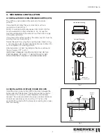
The OPS may be installed in the vertical or horizontal 

position. 
If mounted horizontally, the set-point knob must face 

upwards as shown in Fig. 1.
NOTE: If mounted horizontally, deduct 0.80 inW.C. (20 Pa) 

from the setpoint for offset adjustment.  Do not use this 

mounting arrangement if the setpoint is at the bottom range 

of the pressure switch.
If mounted in the vertical position, the pressure ports must be 

pointing down as shown in Fig. 1.
Secure the switch by using the mounting holes shown in Fig. 

1. Use only two holes located diagonally from each other.  Do 

not over-tighten the mounting screws.
After installation connect the tubing to the stack probe and 

the port marked “P1” and “+”.
IMPORTANT! REMOVE THE PROTECTIVE CAP ON THE 

PORT MARKED “P2” AND “-”. THE SWITCH WILL NOT 

WORK PROPERLY UNLESS IT HAS BEEN REMOVED.

3.2 INSTALLATION OF STACK PROBE FOR OPS

Install the stack probe for the OPS in the stack between the 

boiler outlet and the damper. The probe must be located so 

the distance “A” is at least 3 vent diameters downstream 

damper. The probe placement should also observe distances 

from elbows and tees as shown in Fig. 2. The tip of the 

probe MUST be flush with the inner stack wall to get a proper 

pressure reading.

0.80

(200)

0.72

(180)

0.64

(160)

0.56

(140)

0.48

(120)

0.40

(100)

0.32

(80)
0.24

(60)

0.16

(40)

0.08

(20)

in WC

(Pascal)

Typ 930.80

Mounting Holes

+

-

Horizontal Mounting

Vertical Mounting

+

-

Front

Back

Down

IMPORTANT

Remove protective cap!

Tube to

Probe

EXHAUSTO

P1

+

P2

-

+ -

From 

Appliance

OPS

MDF, Damper

for MODS system

Probe

Venting to

exterior

A

A

Fig 1

Fig 2

Содержание 3903002

Страница 1: ...n Operating Manual ENERVEX OPS OVER PRESSURE SWITCH ENERVEX Inc 1685 Bluegrass Lakes Parkway Alpharetta GA 30004 USA P 770 587 3238 F 770 587 4731 T 800 255 2923 info enervex com www enervex com READ AND SAVE THESE INSTRUCTIONS ...

Страница 2: ...y this manual Please refer to these component s individual manuals TO REDUCE THE RISK OF FIRE ELECTRICAL SHOCK OR INJURY TO PERSONS OBSERVE THE FOLLOWING 1 Use this unit in the manner intended by the manufacturer If you have questions contact the manufacturer at the address or telephone number listed on the front of the manual 2 Before servicing or cleaning the unit switch off at service panel and...

Страница 3: ...hile the EBC 31 control unit drives the damper completely open to relieve the pressure The differential pressure acts via diaphragm against the force of setting spring on the microswitch The pressure switch operates without any auxiliary power The OPS monitors differential pressure in firing and venitlation systems The switch is suitable for air flue and exhaust gases and can be mounted in the hor...

Страница 4: ...C Max Pressure 1 4 PSI 100 mbar Conduit Connection 1 4 Solderless Quick Connect Terminals Pressure Connections Two plastic tubes OD 1 4 6 0mm Weight 0 4lb 0 2 kg Housing NEMA 3 IP 54 1 2 NPT Connection COM 3 P p 1 NC 2 NO OPS Switching Function As pressure rises 1 NC opens 2 NO closes As pressure falls 1 NC closes 2 NO opens Deduct 0 08 inW C 20 Pa from the pressure setting if switch is mounted ho...

Страница 5: ...g to the stack probe and the port marked P1 and IMPORTANT REMOVE THE PROTECTIVE CAP ON THE PORT MARKED P2 AND THE SWITCH WILL NOT WORK PROPERLY UNLESS IT HAS BEEN REMOVED 3 2 INSTALLATION OF STACK PROBE FOR OPS Install the stack probe for the OPS in the stack between the boiler outlet and the damper The probe must be located so the distance A is at least 3 vent diameters downstream damper The prob...

Страница 6: ...oint above normal start up and transition pressures to avoid nuisance trips NOTE On applications where a positive pressure is being maintained a delay timer should be installed to avoid nuisance trips 0 8 0 2 0 0 0 72 1 80 0 64 160 0 56 140 0 4 8 12 0 0 40 1 00 0 3 2 8 0 0 24 60 0 16 4 0 0 0 8 2 0 in WC Pascal Typ 930 80 Use terminals 1 3 for Normally Closed NC 3 2 1 Fig 3 Fig 4 Set Point Indicato...

Отзывы: