Enerpac Pow'r-Riser PR Series Скачать руководство пользователя страница 4

4

WARNING:

 Lift the jack using only lifting eyebolt(s) or 

lifting bar. Never attempt to lift the jack by using the 
handle assembly. The handle assembly is to be used 

only for transporting the jack on its wheels and for positioning 
the jack under the jacking point.

5.  Using the handle assembly, adjust the jack position so that 

the cylinder load cap is centered under the jacking point of 
the load.

WARNING:

 Be sure that the jack is positioned on a 

solid and level support surface, with the lifting cylinder 
perpendicular to the ground. Jacking at an angle can 

allow the jack to slip out of position, resulting in loss of load. As 
required, use a swivel load cap to properly engage angled lifting 
points. Refer to Section 5.5 for additional information.

5.0  OPERATION

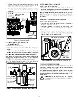
5.1  Control Valves (See Figure 3)

4-Way Manual Valve:

With pump motor running:

•  Move lever to the extend position to raise the cylinder.

•  Move lever to the retract position to lower the cylinder.

•  Center position is neutral/hold. Cylinder stops and holds the 

load. This is also referred to as the 

idle

 position.

4-Way Air Operated Valve with Pendant:

•  To start motor and extend cylinder - press up-arrow button.

•  To start motor and retract cylinder - press down-arrow button.

•  For neutral/hold - release both pendant buttons. Motor will stop.

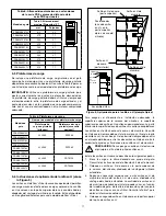
Lifting speed and torque can be regulated by using the air 
pressure regulator. The regulator should be adjusted to 100 psi 
[7 bar] 

maximum

 with air motor running and air supply valve 

completely open.

IMPORTANT:

 Pressure settings of above 100 psi [7 bar] will 

result in reduced air motor life and will void product warranty.

(

)

Manual Valve: Center position is 

NEUTRAL/HOLD

.

Air Operated Valve: Stays in center neutral/hold position

until pendant 

down-arrow

 or 

up-arrow

 button is pressed.

RETRACT

(lower)

RETRACT

(lower)

EXTEND 

(raise)

EXTEND

(raise)

Figure 3, Control Valve and Pendant Details
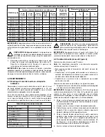
5.2  Jacking Safely

You must know the weight of what you intend to lift and choose 
a jack with 

at least 20 percent 

additional capacity.

All persons operating the jack should obtain and be familiar with 
the 

American National Standards Institute

 rules that apply to 

hydraulic rams and jacks (ASME ANSI B30.1) or the equivalent 
standards used in your country or region.

WARNING: 

Never place any part of your body under the 

load at any time while it is being lifted, lowered, or 
hydraulically supported by the Pow'r-Riser jack.

WARNING:

 The Pow'r-Riser jack is intended for lifting 

purposes only and should not be used to hydraulically 
support the load for any period of time after the lift has 

been completed. Support the load with U-Rings or other suitable 
load supports immediately after it has been lifted to the desired 
height.

WARNING:

 Never leave the Pow'r-Riser jack 

unattended during operation, even for a brief period of 
time. Closely monitor jack operation at all times and be 

prepared to stop lifting or lowering immediately.

WARNING:

 Do not use the Pow'r-Riser jack outdoors in 

windy conditions. Changes in wind direction or velocity 
could cause the load to become unstable and fall.

5.3  Operating Instructions (See Figures 3, 4 and 5)

TO RAISE THE LOAD:

1.  Be certain that the jack is positioned on a solid and level 

surface, capable of supporting the load and the base of 
the jack. Be sure that the lifting cylinder is perpendicular to 
the ground. See Section 4.4 for additional jack positioning 
instructions.

2. 

If a high jacking point requires a taller jack, install extensions 
and spacers (optional accessories) on the cylinder as 
required. Refer to Section 5.4 for installation instructions 
and additional information about extensions and spacers.

3.  Place a piece of plywood or other compression material 

(approximately 1/4" [6,3 mm] thick with good friction 
characteristics) between the cylinder load cap and the 
jacking point. This will provide a small amount of cushioning 
and will also help prevent damage to the jacking point.

4. 

To raise the load, open the air supply valve to start the motor. 
Then, move the control valve lever to the extend position. If 
jack is equipped with pendant, depress the up-arrow button 
to start motor and extend cylinder.

CAUTION:

 When lifting with more than one jack, be 

especially careful to keep the load level. Leveling is best 
accomplished by throttling with the air supply valve or 

by alternating and stopping jacks to keep the load level enough 
so it remains stable.

5. 

When load has reached the desired height, move the control 
valve lever to the center (neutral/hold) position. If jack is 
equipped with pendant, release up-arrow button to return 
valve back to the center (neutral/hold) position.

6.  Be sure that the proper Enerpac U-Rings are installed on 

the cylinder (refer to Section 5.6 for U-Ring installation and 
stacking instructions). If U-Rings are not used, be sure that 
other load supports of appropriate load rating are in place.

7. 

Move the control valve lever to the retract position. Allow the 
load to lower until it is supported by the U-Rings or other 
load supports. Then, return the lever to the center (neutral/
hold) position. If jack is equipped with pendant, depress and 
release the down-arrow button as required, until the load is 
supported by the U-Rings or load supports.

4

Содержание Pow'r-Riser PR Series

Страница 1: ...a margin of safety that accounts for possible shifting loads or side loading conditions DANGER To avoid serious personal injury keep hands and feet away from hydraulic cylinder and related components...

Страница 2: ...PRAMA100__L PRASA100__L 9 700 669 PRASA150__L 10 200 703 PRASA200__L 10 200 703 Load Rating Model US Tons Metric Tons kN PRAMA060__L 60 54 533 PRAMA100__L PRASA100__L 100 90 889 PRASA150__L 150 136 1...

Страница 3: ...s the motor will start automatically when either pendant button is depressed 3 Open the air supply valve callout 4 Using the regulator knob adjust the air pressure to a minimum of 80 psi 5 5 bar IMPOR...

Страница 4: ...y support the load for any period of time after the lift has been completed Support the load with U Rings or other suitable load supports immediately after it has been lifted to the desired height WAR...

Страница 5: ...valve to stop the motor AFTER COMPLETING THE JOB Fully retract the cylinder and close the air supply valve With the motor off shift the control valve several times between the extend and retract posi...

Страница 6: ...compensated for by use of plywood or other suitable compression material alone Table 6 Load Caps Jack Model Load Cap Model Numbers Non Swivel Load Cap standard Swivel Load Cap optional accessory PRAM...

Страница 7: ...Cap Steel U Ring top Recess of U Ring Steel U Ring bottom Aluminum U Rings Locator on each U Ring and at top of cylinder housing Figure 5 U Ring Stacking Arrangement typical 6 0 MAINTENANCE 6 1 Maint...

Страница 8: ...gulator Figure 6 Oil Change 6 3 Air Line Filter Regulator See Figure 7 Every 30 hours of operation Check the lter bowl for water Drain any water if present Inspect air lter element inside lter bowl Re...

Страница 9: ...nsufficient compressed air volume Check air regulator setting Increase volume of compressed air or increase size of supply air line to meet air ow and pressure requirements Internal pressure leaks or...

Страница 10: ...____________________________________________________________ _______________________________________________________________________________________ ___________________________________________________...

Страница 11: ...gato Permitir un margen de seguridad que prevenga la posibilidad de desplazamiento o desviaci n de la carga PELIGRO Para evitar lesiones personales mantenga las manos y los pies alejados del cilindro...

Страница 12: ...l nivel del lubricador para l nea de aire anotaci n 7 y a ada m s lubricante si es necesario Utilice un aceite detergente SAE 10 ISO 32 o un lubricante anticongelante autorizado Consulte la Secci n 6...

Страница 13: ...edas 19 V lvula de aire del neum tico 20 Almacenamiento de los anillos en U No disponible en todos los modelos RAISE LOWER 7 1 15 3 18 19 16 13 5 8 9 7 12 4 10 11 2 14 20 Figura 1 Caracter sticas y co...

Страница 14: ...a corta PRASA20016L est equipado con dos c ncamos para izar Los modelos de carrera corta de la serie PRAMA060 PRA_A100 y PRASA150 no tienen instalados c ncamos para izar ADVERTENCIA Eleve el gato util...

Страница 15: ...ula de control a la posici n central neutral de retenci n Si el gato tiene un mando remoto libere el bot n de la echa hacia arriba para que la v lvula vuelva a la posici n central neutral de retenci n...

Страница 16: ...pcionales Modelo de piezas de distancia Anchura de cada uno mm Pulgadas PRS1 25 1 PRS2 51 2 PRS3 76 3 Conjunto de piezas de distancia PRS4 El conjunto incluye PRS1 PRS2 y PRS3 1 cada uno PRECAUCI N Nu...

Страница 17: ...cilindro extendido Est n disponibles en 5 longitudes diferentes para cada modelo de Pow r Riser Assembled View Anillo de soporte de carga Plataforma de carga Anillo en U de acero parte superior Anillo...

Страница 18: ...alcance los 60 C 150 F Cuando haya un alto grado de humedad en el entorno y o cambios de temperatura extremos que puedan provocar la condensaci n del aceite dentro del dep sito Cuando haya un entorno...

Страница 19: ...lenciador v ase la gura 8 Cada 30 horas de funcionamiento Compruebe que no haya suciedad en el silenciador Si est obstruido reemplace el silenciador por uno nuevo que tenga las mismas especi caciones...

Страница 20: ...r ulico en un centro de servicio t cnico autorizado Enerpac Repare o sustituya los componentes seg n sea necesario Ajuste demasiado bajo de la v lvula de descarga interna o de la v lvula de alivio en...

Страница 21: ...____________________________________________________________ _______________________________________________________________________________________ ___________________________________________________...

Страница 22: ...____________________________________________________________ _______________________________________________________________________________________ ___________________________________________________...

Страница 23: ...____________________________________________________________ _______________________________________________________________________________________ ___________________________________________________...

Страница 24: ...7 495 98090 92 sales ru enerpac com Singapore Actuant Asia Pte Ltd 83 Joo Koon Circle Singapore 629109 T 65 68 63 0611 F 65 64 84 5669 Toll Free 1800 363 7722 sales sg enerpac com South Korea Actuant...

Отзывы: