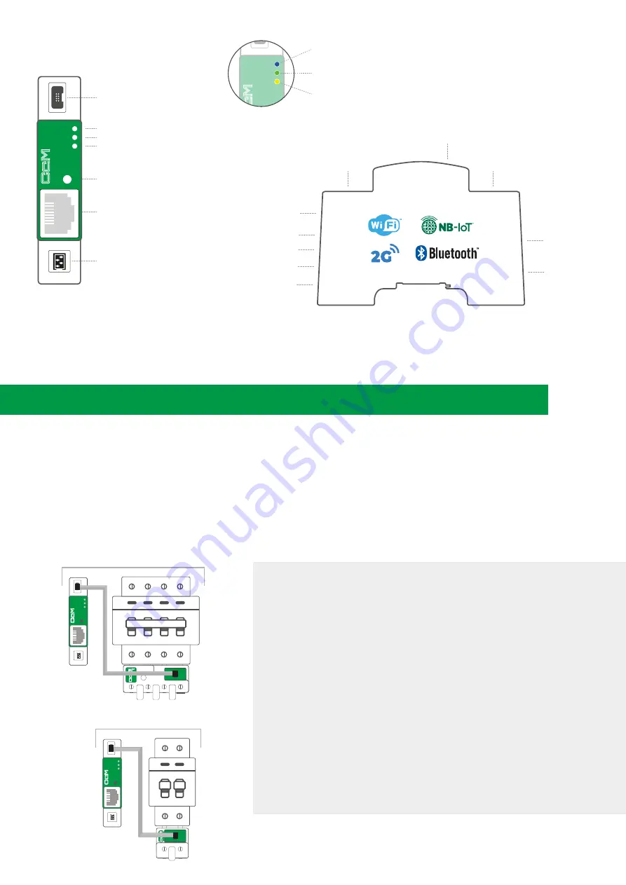
1. POWER THE CcMASTER FROM A PRINCIPAL CCM DEVICE
The 8-wire cable supplied with the CcMaster device, shall be connected as follows:
a.
The green end with the two-connector adapter, connected to the CcM Principal device (CcM2 or CcM4)
b.
The black 8-pin connector, connected to the NDsp connector of the CcMaster
(notes 1,2,3)
Once the 8-wire cable is connected to the NDsp connector, the CcMaster will start up. An initial blink on the blue LED,
A, and a blink every two seconds of the green LED, B.
NOTE 1:
The NDsp connector of the CcMaster has an unambiguous connection format for
connecting the 8-wire cable.
NOTE 2:
The 8-wire cable connected to the NDsP connector provides power to the CcMaster
through the Principal CcM device and allows the CcMaster to acquire the data from that device.
NOTE 3:
The NDsp connector only allows only 1 Principal CcM to be connected, being by default
the device with ID Modbus ‘1’ address and the one that give power to the CcMaster.
NOTE 4:
The rest of the Principal CcM devices, up to 32, will be connected via cable through the
second native connector (ND), as described later in the manual.
NOTE 5:
If Secondary CcM devices are to be connected, these must be connected to any other
Principal CcM device that hangs from the bus that terminates in the ND connector (see CcM1-C
and CcM3-C manual).
NOTE 6:
Up to 10 Principal CcM devices more may be connected, via a CcM Wifi device, apart from
the 32 Principal CcM devices connected via cable, as described later in the manual.
NOTE 7:
It is recommended to perform this entire connection process after activating the
protection device to prevent voltage from reaching the devices.
2
Connections
Installation Steps
Led A (blue)
Multifunction button
Led B (green)
Led C (yellow)
Ethernet connection
NDsp
Native data port of the Principal CcM
analyzers and self-powered
ND
Native data port of the
Principal CcM analyzers
aster
Native data port of the
Principal CcM analyzers
and self-powered
NDsp
Native data port of the Principal
CcM analyzers
ND
Conexión Ethernet
0-10V Output
Digital outputs
RS-485 port
Communications
antenna
Auxiliary power
SIM
RS-232 port
Dynamic Assignment Mode
Off: read mode. Blink every second: dynamic assignment mode. Quick blinking: firmware
update.
Internet and data server
Flashing every second indicates no connection, 1 flash every 3 seconds indicates that it
has an internet connection and 2 flashes every 3 seconds that it has a connection to the
data server.
GPRS modem
Off: modem disconnected. Flash every 2 seconds: searching for mobile network. Fixed:
modem registered to network. Flashing when data traffic.
aster
NDsp
Option A
(three phase) with CcM4
aster
ND
Option B
(one phase) with CcM2
aster
NDsp
ND


