background image

Products

Solutions

Services

Brief Operating Instructions

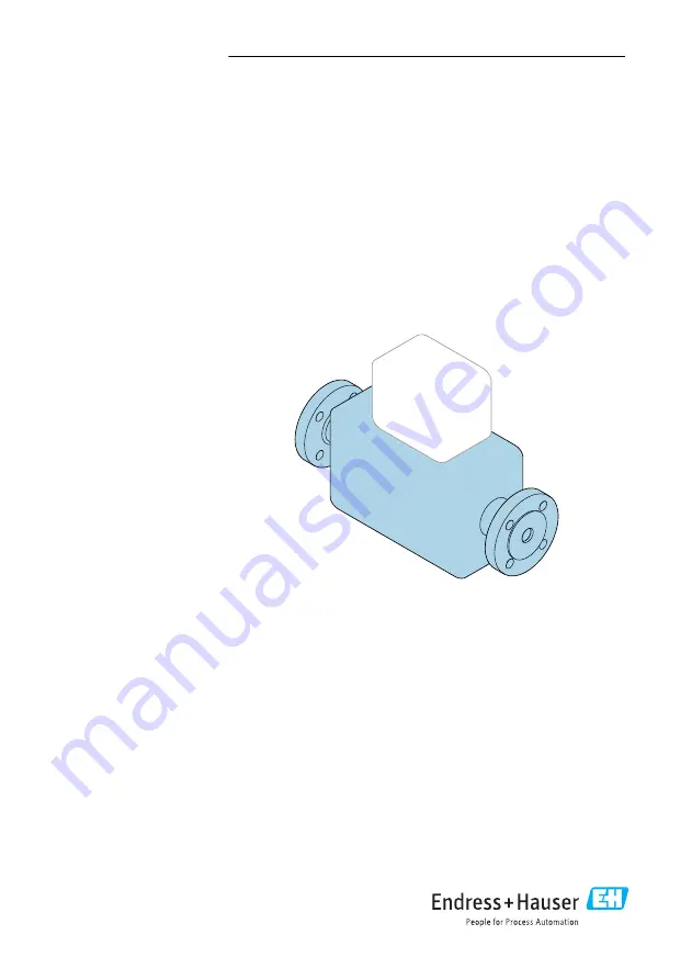
Proline Prosonic Flow P

Ultrasonic time-of-flight sensor

These instructions are Brief Operating Instructions; they are

not

 a substitute for the Operating Instructions pertaining to

the device.

Brief Operating Instructions part 1 of 2: Sensor

Contain information about the sensor.
Brief Operating Instructions part 2 of 2: Transmitter

→   3.

KA01474D/06/EN/01.21

71508892

2021-05-10

Содержание Proline Prosonic Flow P

Страница 1: ...These instructions are Brief Operating Instructions they are not a substitute for the Operating Instructions pertaining to the device Brief Operating Instructions part 1 of 2 Sensor Contain informatio...

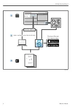
Страница 2: ...Proline Prosonic Flow P 2 Endress Hauser Order code Ext ord cd Ser no www endress com deviceviewer Endress Hauser Operations App XXXXXXXXXXXX XXXXX XXXXXX XXX XXXX XX Serial number 1 3 2 A0023555...

Страница 3: ...device Incoming acceptance and product identification Storage and transport Installation Brief Operating Instructions Part 2 Transmitter The Transmitter Brief Operating Instructions are aimed at spec...

Страница 4: ...l safety 8 2 5 Product safety 8 2 6 IT security 8 3 Incoming acceptance and product identification 8 3 1 Incoming acceptance 8 3 2 Product identification 9 4 Storage and transport 10 4 1 Storage condi...

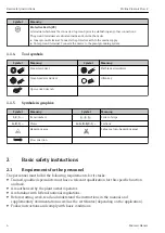
Страница 5: ...n on procedures and other facts which do not result in personal injury 1 1 2 Symbols for certain types of information Symbol Meaning Symbol Meaning Permitted Procedures processes or actions that are p...

Страница 6: ...wrench 1 1 5 Symbols in graphics Symbol Meaning Symbol Meaning 1 2 3 Item numbers 1 2 3 Series of steps A B C Views A A B B C C Sections Hazardous area Safe area non hazardous area Flow direction 2 Ba...

Страница 7: ...ardous area e g explosion protection pressure vessel safety If the ambient temperature of the measuring device is outside the atmospheric temperature it is absolutely essential to comply with the rele...

Страница 8: ...rements It also complies with the EU directives listed in the device specific EU Declaration of Conformity Endress Hauser confirms this by affixing the CE mark to the device 2 6 IT security Our warran...

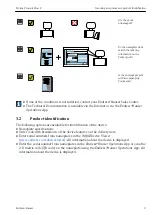
Страница 9: ...ia the Internet or via the Endress Hauser Operations App 3 2 Product identification The following options are available for identification of the device Nameplate specifications Order code with breakd...

Страница 10: ...lowing notes for storage Store in the original packaging to ensure protection from shock Protect from direct sunlight to avoid unacceptably high surface temperatures Store in a dry and dust free place...

Страница 11: ...orientation with upward direction of flow B Non recommended installation range with horizontal orientation 30 C Recommended installation range max 120 Vertical Recommended orientation with upward dir...

Страница 12: ...tlet runs indicated below must be maintained at the very minimum in order to attain the specified level of accuracy of the measuring device If there are several flow disturbances present the longest s...

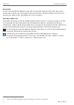
Страница 13: ...ol valve 2 3 open 6 Pump 5 1 2 Environment and process requirements Ambient temperature range For detailed information on the ambient temperature range see the Operating Instructions for the device If...

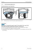
Страница 14: ...engineering unit mm in Cover locking NOTICE Order code for Transmitter housing option L Cast stainless The covers of the transmitter housing are provided with a borehole to lock the cover The cover c...

Страница 15: ...uring device 5 2 1 Required tools For transmitter Proline 500 For mounting on a post Proline 500 transmitter Open ended wrench AF 13 For wall mounting Drill with drill bit 6 0 mm For sensor For instal...

Страница 16: ...traverses mm in Sensor distance 1 Sensor distance 1 Sensor distance 1 Sensor distance 1 Sensor distance 1 Wire length 27 Measuring rail 1 2 Wire length Measuring rail 1 2 1 Depends on the conditions...

Страница 17: ...e tightened too much The use of a metal half shell on the opposite side of the sensor is recommended for plastic or glass pipes The visible measuring pipe surface must be clean free from flaking paint...

Страница 18: ...r and measuring pipe without twisting them 1 A0043371 6 Positioning the sensor holder and mounting the strapping bands 1 Sensor holder 4 Guide the strapping bands through the strapping band locks 5 Ti...

Страница 19: ...ble gloves and protective goggles The visible measuring pipe surface must be clean free from flaking paint and or rust to ensure good acoustic contact Sensor holder with strapping bands medium nominal...

Страница 20: ...strapping band 2 for final alignment 9 If necessary shorten both strapping bands and trim the cut edges LWARNING Risk of injury To avoid sharp edges trim the cut edges after shortening the strapping b...

Страница 21: ...2 in of one of the strapping band ends through one of the two strapping band locks and into the buckle Then guide the protective flap over this strapping band end and lock in place 5 Position strappi...

Страница 22: ...e same height clock position e g 10 and 4 o clock in relation to the two strap bolts on tensioning strap 1 A line drawn on the measuring pipe wall that is parallel to the measuring pipe axis can be he...

Страница 23: ...DN 50 to 4000 2 to 160 Procedure The welded bolts must be fixed at the same installation distances as the mounting bolts with strapping bands The following sections explain how to align the mounting b...

Страница 24: ...ad or coupling gel for an acoustic connection between the sensor and pipe Procedure 1 Set the distance between the sensors to the value determined for the sensor distance Press the movable sensor down...

Страница 25: ...Proline Prosonic Flow P Installation Endress Hauser 25 3 Fit the sensor housing on the sensor holder A0043377 13 Fitting the sensor housing...

Страница 26: ...ng cables The visible measuring pipe surface must be clean free from flaking paint and or rust to ensure good acoustic contact If necessary the holder and sensor housing can be secured with a screw nu...

Страница 27: ...he two measuring wires arrange the cable lugs and fixer such that the distance they are apart corresponds to the wire length SL Screw the fixer onto the measuring wire 1 2 3 4 5 6 7 8 9 10 11 SL A0043...

Страница 28: ...the distance is too small release strapping band 2 again and position it better Both strapping bands should be as perpendicular as possible to the measuring pipe axis and parallel to one another A0043...

Страница 29: ...f coupling gel approx 1 mm 0 04 in going from the groove through the center to the opposite edge A0043382 18 Coating the contact surfaces of the sensor with coupling gel if there is no coupling pad 8...

Страница 30: ...h measuring pipe surfaces the gaps in the rough surface must be filled with sufficient amounts of coupling gel if the use of the coupling pad does not suffice installation quality check Installation f...

Страница 31: ...lt sensor distance measuring aid parameter over the mounting bolt of strapping band 1 that is fixed in place Position the adjustable strapping band 2 and fit the mounting rail with the bore identified...

Страница 32: ...atively coat the contact surfaces with an even layer of coupling gel approx 1 mm 0 04 in going from the groove through the center to the opposite edge A0043382 22 Coating the contact surfaces of the s...

Страница 33: ...must be cleaned and new coupling gel applied if there is no coupling pad On rough measuring pipe surfaces the gaps in the rough surface must be filled with sufficient amounts of coupling gel if the us...

Страница 34: ...Installation Proline Prosonic Flow P 34 Endress Hauser Wall mounting 20 0 79 100 3 94 100 3 94 8 6 0 39 18 0 71 10 0 39 A0029068 24 Engineering unit mm in...

Страница 35: ...ery heavy They are unstable if they are not mounted on a secure fixed post Only mount the transmitter on a secure fixed post on a stable surface 1 4 x SW 13 0 79 to 2 75 20 70 A0029057 25 Engineering...

Страница 36: ...rsion Loosen the securing clamp of the connection compartment cover 2 Unscrew the connection compartment cover 3 Release the fixing screw 4 Turn the housing to the desired position 5 Tighten the fixin...

Страница 37: ...position max 8 45 in each direction 4 Screw on the connection compartment cover 5 Depending on the device version Attach the securing clamp of the connection compartment cover 5 3 Post installation ch...

Страница 38: ...sposal under the applicable conditions 6 1 Removing the measuring device 1 Switch off the device LWARNING Danger to persons from process conditions Beware of hazardous process conditions such as press...

Страница 39: ......

Страница 40: ...www addresses endress com 71508892 71508892...

Отзывы: