Float Gauge LTC2230/LTC2240
12
Hauser
4
Installation Adjustment
4.1
Wave Guard
1.
Use the following specifications for wave guards; 6B, SGP, jointless, and white pipe.
2.
Completely remove burrs from weld joints and from the inside of pipe joints that have been cut and
rewelded.
3.
Be sure that airtightness is maintained in the flange between wave guard and gauge head.
4.2
LTC Installation
Installation Procedure
1.
Remove the rear cover of gauge head [6].
2.
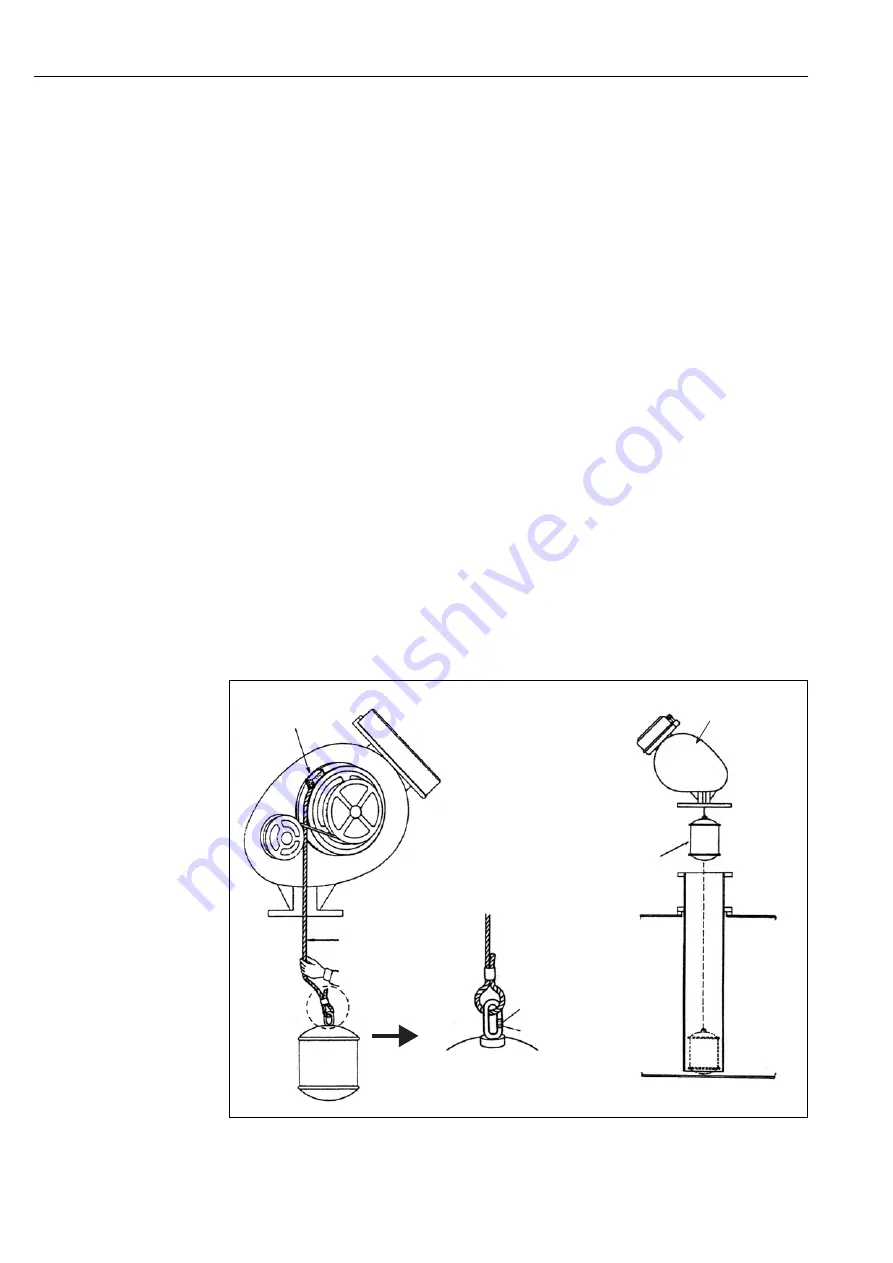
Hold the measuring wire [2] by hand and remove the fixing sponge [1] (black, Approx, 16 x 16 x 16mm).
3.
Pull on the measuring wire to connect the float [5].
•
As the float begins to weigh down on the measuring wire (1.2kg), confirm that the float is securely
connected to the measuring wire before releasing.
4.
Move the crimp sleeve [4] upward and connect the measuring wire to the float.
5.
Move the crimp sleeve downward and crimp the center of the sleeve so that the measuring wire does not
disconnect from the float.
6.
Hold on to the measuring wire and lower the float slowly into the wave guard.
7.
When the float reaches the bottom of the tank, install the gauge head.
8.
Replace the rear cover.
This completes the installation procedure.
Figure 5:
LTC Gauge Head Installation
Fixing Sponge [1]
Gauge Head [4]
Float [5]
Crimp Sleeve [3]
Crimping Part
Measuring Wire [2]
4 Installation Adjustment


