Step 3
- Next for a more detailed test and to confirm your PoE Equipment works with the 865X PRO, connect
your Ethernet LAN to the 395 PoE Injector and the remote PoE device/s to the remote 865X PRO
LAN port and test connectivity. The Green Interlink Sync LED will pulse rapidly as it detects
traffic.
Performing the On-Site Installation
After removing the Enable-IT 865X PRO Gigabit PoE Extender Kit from the box, and performing
the Out Of The Box Testing (OOTBT), all that remains to install the unit on-site is to mount the
unit, build the interconnect wiring, add voice lines if needed, and attach the LAN device cabling
with the provided Ethernet Patch cords.
Mounting the Enable-IT 865X PRO Gigabit PoE Extender Units
The Enable-IT 865X PRO extended Ethernet solution is designed for quick wall mounting.
Choose a location to mount each of the Enable-IT 865X PRO’s where the maximum distance
does not exceed 3,000ft (915m) total between devices to be connected. When wall-mounting
the Enable-IT 865X PRO unit it is recommended that you use the appropriate screw anchors for
your mounting surface. If mounting on existing plywood use wood screws; if mounting onto
drywall or sheetrock, use plastic drywall anchors to secure your installation.
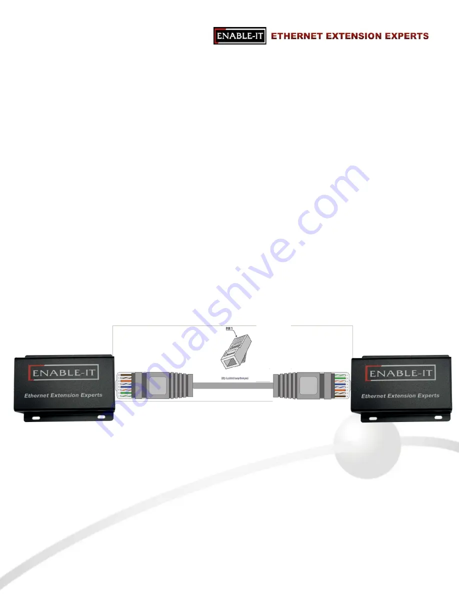
Building the 865X PRO Interlink Wiring
The most important aspect of the installation is the correct wiring of the Interlink cabling.
For all wiring you will need to crimp a (LAN Standard) RJ-45 Male head to each end of the
contiguous wire run and using the following TIA 568B straight through standard. We recommend
using a category rated 100MHz or better twisted pair cable as it is optimized for high throughput
frequencies isolated from cross-talk noise. Insert the completed RJ-45 ends into the 865X PRO
Interlink port on each 865X PRO unit.
Cabling Devices to The Enable-IT 865X PRO Extended Ethernet Kit
Attach your remote PoE device to the 865X PRO CPE unit LAN ports with Ethernet patch cord
provided. Attach your local LAN to the 395 PoE Injector with Ethernet patch cord provided.
Attach the power adapters to both 865X PRO units.
Attach your local Interlink cabling end to the 865X PRO CO unit Interlink port – Then do the
same for the remote end and plug into the 865X PRO CPE unit Interlink port. The Sync LED’s
will flicker in a sequence talking to each other until they go solid. Your equipment should now
be powered up and functioning. LED indicators will provide visual operational status of the
865X PRO units.
All Rights Reserved © 1997 - 2020 Enable-IT
™
, Inc. Page of
3
7
865X PRO CPE
865X PRO CO
RJ-45 Interlink Cabling up to 3,000 feet / 915m


