Emulex OneConnect OCe10102 CNA Installation Manual
Page 4
8.
Remove the bracket and store it for future use.
9.
Align the new mounting bracket tabs with the holes in the CNA.
10. Re-install the screws that attach the CNA to the bracket.
11. Re-install the transceiver by sliding it into the housing. When the latch engages, it clicks.
12. Push the bail back into place.
Installing the Adapter
1.
Turn off and unplug the computer.
2.
Remove the computer case.
3.
Remove the blank panel from an empty PCIe bus slot. See “Preparing the CNA for Installation” on
page 2 to change the brackets if needed. Otherwise, skip to “Attaching Media” on page 4.
4.
Insert the CNA into the empty x8 or x16 PCIe bus slot. Press firmly until the adapter is seated.
5.
Secure the CNA's mounting bracket to the case with panel screw or clip.
6.
Replace the computer case and tighten case screws.
The CNA is now installed in the server and is ready for media attachment.
Attaching Media
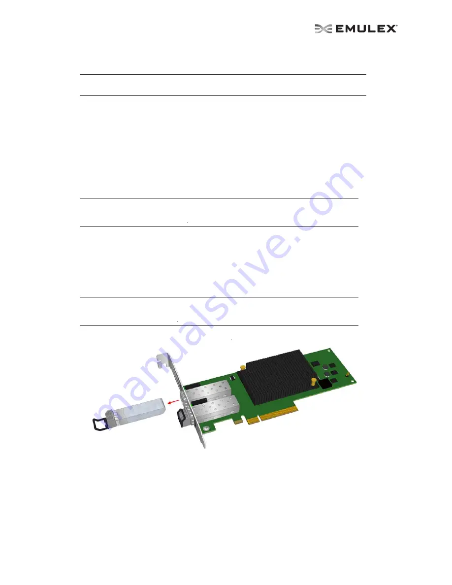
Figure 5 shows the CNA and the optical transceivers.
Figure 5: CNA with Optical Transceivers
Note:
Be careful not to push the bracket past the transceiver housing's grounding tabs. Make
sure the light emitting diodes (LEDs) are properly aligned with the holes in the bracket.
Note:
Place the CNA into an empty PCIe x8 or x16 slot. Make sure that the adapter is in an
appropriate PCIe slot that does not interfere with other components or case to
prevent damage to the CNA.
Note:
A CNA does not allow normal data transmission on either 10 Gb optical or copper link
unless it is connected to a compatible optical or copper interface connection (that is,
multimode to multimode).


