28
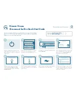
15.6 Circuit Diagram – SOFT START (200 TO 240 V OPERATION)
NOTE:
For 110 – 120 V operation, C1 is replaced by a 3900 ohm / 5 Watt resistor
PH
ASE
C6 2.
2nF
MT1
R1
100/
2W
R6 270k
D1
1N
4007
GAT
E
R4 150/
2W
LOAD
C1
0
100nF
C9 100nF
U1
1
2
3
4
5
6
7
8
9
10
11
12
13
14
15
16
CS
VS
CL
AS
SS
RC
RG
T
GND
VCC
SR
PC
DS
S
TP
A
SCA
P
SSC
LS
+
C5 220uF
/25V
SW
IT
C
H
MT2
R8
470k
/2
W
C3 2.
2nF
NOTE: 200V to 240V
operation
R1
0
100k
D2
1N
4007
+
C4 220uF
/25V
For 110VAC, replace
C1 by 3.9k or 4.
3k / 6W
resistor
R7 470k
/2
W
R9
10k
E M T R
O N
C1
470nF
/250Vac
/X
2
C1
1
2.
2nF
R1
100/
2W
LOAD
C1
2
100nF
C2 220nF
/250Vac
/X
2
+
C8 3.
3uF
NE
UT
RA
L
C7 47nF
C1
3
4.
7nF
/250Vac
/Y
2
SW
IT
C
H
R2 56R
/2
W
R3
220/
2W
R2 56R
/2
W
SOF
TST
AR
T2
40V
4
SO
FT S
TA
R
T
A4
11
M
onday
, J
anuary
07,
2002
Ti
tle
Siz
e
D
oc
um
ent
N
um
ber
R
ev
D
at
e:
S
heet
of
C1
4
4.
7nF
/250Vac
/Y
2