background image


EMS Group Head Office, Technology House, Sea Street, Herne Bay, Kent CT6 8JZ, England 

Tel: +44 (0) 1227 369570 Fax: +44 (0) 1227 369679 Email: 

[email protected]

  Website: 

www.emsgroup.co.uk


Ziton Radio Loop Module Programming Manual (Issue 7d) TSD022                                                        

22 

5.5  Viewing the Radio Loop Modules Status 


Enter the menu structure by pressing the rotary control.


Turn the rotary control until the display shows; 


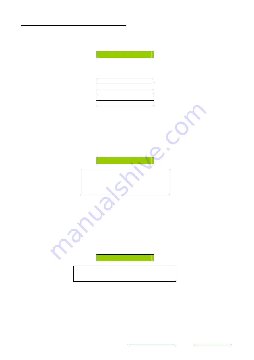
Interface Status 


For  more  detailed  information  on  the  device  displayed  press  the  rotary  control.    The  list  of 
available information is shown in the following format;


Fault Status 
Background Level 
Ident xxxxx 
Software Vxx.xx 

Serial Data 


Note:  The  Serial  Data  option  is  only  available  when  the  Ziton  Radio  Loop  Module


has 

switch  8  on.    This  enables  Serial  Data  to  be  seen  on  a  terminal  programme  via  the 
onboard serial port. If either of these options are selected it is important NOT to leave 
the Radio Loop Module in this diagnostic / operational mode. 


To enter the Fault Status Menu press the rotary control with the Fault Status text displayed.  
The display will change to show the current Fault status of the Radio Loop Module, an example 
is shown below;


No Fault Present 


Available Options are;  
No Fault Present 
 Aerial Tamper 
Ch1 RFI Det   
Ch2 RFI Det


Note:  If multiple faults are applicable to the Radio Loop Module the rotary control can be turned 
to view the total fault listing and a down arrow will be present to indicate that there is more than 
one fault present. 


The menu will timeout after 30 seconds or alternatively press the Back button to immediately 
return to the previous Menu.


To enter the Background Level Menu press the rotary control with the Background Level text 
displayed.  The display will change to show the current Background Level for the two channels 
used.  The levels are updated in real time.  An example display is shown below;


Ch1    0 


Available Options are;  
Ch1 (With Levels 100 -0 displayed) 
Ch2  (With Levels 100 -0 displayed)


The Levels shown represent 5 levels these are interrupted as follows;


100 shown indicates VERY HIGH


75 shown indicates HIGH


50 shown indicates MEDIUM


25 shown indicates LOW


0 Bar shown indicates GOOD.


Note:  Turn the rotary control to view the background level of the second channel used. 


Содержание ZITON RADIO LOOP MODULE

Страница 1: ...ZITON RADIO LOOP MODULE PROGRAMMING MANUAL ...

Страница 2: ...n 3 1 2 Handling Precautions 3 1 3 Packaging 3 2 0 MENU STRUCTURE 4 2 1 Menu Structure Layout 4 3 0 MENU EXPLANATION 5 3 1 Device Status 5 3 2 Add New device 12 3 3 Remove device 13 3 4 Interface Status 13 3 5 Radio Channels 14 4 0 FRONT DISPLAY OF RADIO LOOP MODULE 14 5 0 ACCESSING THE RADIO LOOP MODULES MENUS 14 5 1 Viewing the Device Status 15 5 2 Output Test 19 5 3 Adding New Devices to the Sy...

Страница 3: ...tallation work should be carried out in accordance with the survey and system design It is recommended that the Ziton Radio Loop Module and peripheral devices are located in accordance with the radio survey and system design This should be established before installation work commences 1 2 Handling Precautions General Care should be taken when handling Ziton Radio Loop Module Avoid dropping any of...

Страница 4: ...at a time at 30 second time intervals 2 1 Menu Structure Layout Front Screen Device Status Device Address Fault Status Add New Device Alarm Status Remove Device Battery Level Interface Status Signal Level Radio Channel Manual Update Ident Software Version Loop Address Output Test Fault Status Background Level Ident Software Version Node Number Audio Detect Batt Smooth Serial Data Currently Used Sc...

Страница 5: ...s example this indicates the devices loop address number which has been selected Available options are between 1 and 127 L In this example this field indicates the devices logged on or fault status Available options are L Logged On and in a normal condition Logged On with fault s present Logged On with a fire alarm present Logged On with a pre alarm present Multi This field indicates the device ty...

Страница 6: ... 080 075 Input Output 090 085 080 075 In Tamper this indicates that the devices tamper switch is not currently making contact against the ceiling or wall mounted base plate The analogue value seen on the Fire Alarm Control Panel for devices in this state is Analogue Value Slot 5 Slot 6 Detector N A 181 Manual Call Point N A 181 Sounder N A 181 Input Output N A 181 Head Missing this indicates that ...

Страница 7: ... this shows that the device has either a low battery and has a minimum operational life of 7 30 days or has a battery missing The analogue value seen on the Fire Alarm Control Panel for devices with low batteries is Analogue Value Slot 5 Slot 6 Detector N A 213 Manual Call Point N A 213 Sounder N A 213 Input Output N A 213 The analogue value seen on the Fire Alarm Control Panel for devices with a ...

Страница 8: ...this state is Analogue Value Slot 5 Slot 6 Detector N A N A Manual Call Point N A N A Sounder N A N A Input Output N A 118 Open Circuit this indicates that an input has a short circuit wiring fault The analogue value seen on the Fire Alarm Control Panel for devices in this state is Analogue Value Slot 5 Slot 6 Detector N A N A Manual Call Point N A N A Sounder N A N A Input Output N A 118 Alarm St...

Страница 9: ...l state is Analogue Value Slot 5 Slot 6 Detector N A N A Manual Call Point N A N A Sounder N A N A Input Output 090 244 The analogue value seen on the Fire Alarm Control Panel for devices with inputs in the closed state is Analogue Value Slot 5 Slot 6 Detector N A N A Manual Call Point N A N A Sounder N A N A Input Output 213 N A Battery Level this menu when entered shows information on the batter...

Страница 10: ...al that has been sent from the Radio Loop Module to the device The LI Dev level is updated every 6 hours or when requested manually by selecting the Manual Update Option from the menu Ch 1 LI Dev this indicates the received signal strength at the Radio Loop Module from the device on the first frequency channel used by the system A level from 100 0 is shown to indicate the levels a table of which i...

Страница 11: ...device information is automatically updated every 6 hours or if a manual update is requested The minimum recommend level is 50 points or above on each channel Manual Update This menu when entered will automatically send signals from the Radio Loop Module to the individual device and ask for its current signal level status to be transmitted back to the Radio Loop Module This will then automatically...

Страница 12: ...o devices to the Radio Loop Module A maximum of 31 devices are allowed When this menu is entered the log on button must be pressed on the new device A confirmation of the device ident number is requested and when accepted will add the device to the Radio Loop Module The log on button can be found on the devices in the following locations Detector Log On Button Sounder Log On Button Callpoint Log O...

Страница 13: ...in any fault and is operating normally The analogue value seen on the Fire Alarm Control Panel for this state is Analogue Value Slot 5 Slot 6 Radio Loop Module 090 244 Ch1RFI Det this description indicates that a radio frequency interference signal has been detected on radio channel 1 that the system is operating on Ch2 RFI Det this description indicates that a radio frequency interference signal ...

Страница 14: ...h12 868 323 MHz Ch20 868 825 MHz Ch28 869 025 MHz Ch5 868 148 MHz Ch13 868 349 MHz Ch21 868 850 MHz Ch29 869 050 MHz Ch6 868 173 MHz Ch14 868 374 MHz Ch22 868 875 MHz Ch30 869 075 MHz Ch7 868 198 MHz Ch15 868 399 MHz Ch23 868 900 MHz Ch31 869 100 MHz Ch8 868 223 MHz Ch16 868 424 MHz Ch24 868 925 MHz Ch32 869 125 MHz 4 0 FRONT DISPLAY OF RADIO LOOP MODULE The front display of the Ziton Radio Loop M...

Страница 15: ... example this field indicates the devices logged on or fault status Available options are Multi This field indicates the device type Available options are Radio Radio Loop Module Module Multi Multisensor Detector Optic Optical Detector Heat Heat Detector HTemp Heat Detector MCP Manual Callpoint Sound Sounder Device I O Input Output Device Unknown Device For more detailed information on the device ...

Страница 16: ...Menu press the rotary control with the Alarm Status text displayed The display will change to show the current Alarm status of the device an example is shown below In Fire Available Options are No Alarm Present In Fire In Pre Alarm The menu will timeout after 30 seconds or alternatively press the Back button to immediately return to the previous Menu To enter the Input Status Menu This is only ava...

Страница 17: ...re indicating the signal that has been sent from the device to the Radio Loop Module The LI Dev level is updated every poll 123 seconds The forward signal strength received at a device from the Radio Loop Module is shown as an LI Dev level therefore indicating the signal that has been sent from the Radio Loop Module to the device The LI Dev level is updated every 6 hours or when requested manually...

Страница 18: ...control whilst in the Device Status Menu until the following example display is shown Software V 1 77 The menu will timeout after 30 seconds or alternatively press the Back button to immediately return to the previous Menu To select the Manual Update function turn the rotary control whilst in the Device Status Menu until the following example display is shown Manual Update Press the rotary control...

Страница 19: ...desired device number Press the rotary control The following screen should be displayed Turn the rotary control until the display shows Press the rotary control and the display will change to show To switch on the output turn the rotary control until the display shows The devices LED should activate To switch the output off turn the rotary control until the display shows The menu will timeout afte...

Страница 20: ...xxx Y To add the device press the rotary control and the display will change to show The screen will now display Turn the rotary control until the desired device number is shown Press the rotary control and the display will change to show Detector Added 01 represents the device slot in which the new device has been allocated Available options are between 01 31 The Det represents the new device all...

Страница 21: ...ack button to revert to the Add Device Menu 5 4 Removing Device from the System Enter the menu structure by pressing the rotary control Turn the rotary control until the display shows Remove Device Press the rotary control and the display will change to show the devices allocated onto the Radio Loop Module The list can be viewed by turning the rotary control The information is shown in the followi...

Страница 22: ...ault Status text displayed The display will change to show the current Fault status of the Radio Loop Module an example is shown below No Fault Present Available Options are No Fault Present Aerial Tamper Ch1 RFI Det Ch2 RFI Det Note If multiple faults are applicable to the Radio Loop Module the rotary control can be turned to view the total fault listing and a down arrow will be present to indica...

Страница 23: ...he rotary control button to toggle the option between OFF and ON The menu will timeout after 30 seconds or alternatively press the Back button to immediately return to the previous Menu Note The Serial Data option is only available when the Ziton Radio Loop Module has switch 8 on This enables Serial Data to be seen on a terminal programme via the onboard serial port If either of these options are ...

Страница 24: ...tely return to the previous Menu To select the auto select option from the radio channels menu Turn the rotary control until the display shows Auto Select Press the rotary control and the display will change to show the time duration the scan is to take place for An example is shown below Scan Time 1min Available Options are 1 min 5 min 10 min 20 min 30 min 60 min Turn the rotary control until the...

Страница 25: ...e required channel is shown and press the rotary control to select The display will change to show the 32 available channels in the following format Ch1 868 048Mhz Available channels for selection are shown below Ch1 868 048 MHz Ch9 868 248 MHz Ch17 868 749 MHz Ch25 868 950 MHz Ch2 868 073 MHz Ch10 868 273 MHz Ch18 868 774 MHz Ch26 868 975 MHz Ch3 868 098 MHz Ch11 868 298 MHz Ch19 868 800 MHz Ch27...

Страница 26: ...tion The information contained within this literature is correct at time of publishing The EMS Group reserves the right to change any information regarding products as part of its continual development enhancing new technology and reliability The EMS Group advises that any product literature issue numbers are checked with its head office prior to any formal specifications being written ...

Отзывы: