


4
Introduction
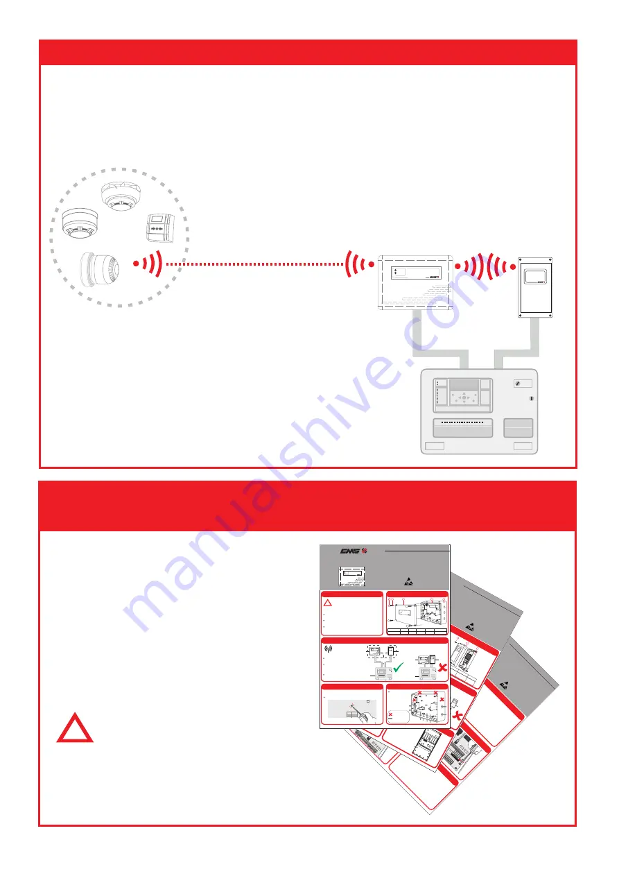
The EMS Wireless Zone Monitor (WZM) allows for 30 FireCell wireless devices to be
added to an existing Fire Alarm Control Panel, in conjunction with an EMS Zone
Interface Module (ZIM).
Existing
Fire Alarm
Control Panel
ww
w .emsg
roup
.co
.uk
Radio D
etec
tor Base
PRESS HERE T
O
L OG ON
IDENT
FireCell
Wireless
Devices
Wireless
Zone
Monitor
(WZM)
POWER
FAULT
WIRELESS ZONE MONITOR
Zone
Interface
Monitor
(ZIM)
WIRELESS ZONE INTERFACE MODULE
FIRE
Fire Alarm Control
Step 1:
Install the WZM and the ZIM
Refer to the EMS Wireless Zone Monitor
Installation Guide (TSD141) and the EMS
Zone Interface Monitor Installation
Guide (TSD142) for full information.
If connecting to a Conventional Fire
Alarm Control Panel, also follow the
Conventional Interface Card Installation
Guide (TSD147).
Installation
©2014 EMS
R
adio
Fire &
S
ecurit
y S
ystems
Ltd. All rights reserv
ed
1/2
T
SD
147
Iss
2 11/08/14
AJM
Step 1
Intro
ductio
n
St
ep 6
Connect
ion Wiring
St
ep 2
Pre Inst
allatio
n
Part No
Pro
duct
Descript
io
n
ATTENTION
OB
SERVE PRECA
UTIONS
FOR HA
ND
LING
ELECTROST
ATIC
SENSITIVE
EC
-63-0001
EMS
Con
ventiona
l Interface
Card
Conventio
nal Interface Card (CIC)
Inst
allat
io
n Guide
Step 3
Connect
CIC t
o t
he ZIM
Step 5
Fasten t
he ZIMs Terminals
SOUNDERS
FAU
LT
ZONE/RESE
T
EO
L
L1 L2
EOL
L1 L2
ALA
RM
RES
EOL
L1 L2
(+) (-)
(+) (-)
(+) (-)
(+) (-)
(+) (-)
(+) (-)
(+) (-)
SO
UN
DER
S
FAU
LT
ZONE/RESE
T
EOL L1 L2
EOL L1 L2
ALARM
RES
EOL L1 L2
The CIC
can be
wired
in two diff
erent
wa
ys.
Fault
notifica
tion
can
either
be
monitored
via
the
Con
ventional
FAPs
Sounder
or
Zone Circuit.
See o
verleaf
for
the
alterna
tiv
e wiring
methods.
SOUNDER
FAU
LT
ZO
NE
EOL L1 L2
EOL L1 L2
ALARM
RES
EOL L1 L2
SOUNDERS
FAU
LT
ZONE/RESE
T
EOL L1 L2
EOL L1 L2
ALARM
RES
EO
L L
1 L
2
Ensure the pins line up with the ZIMs terminal connections as
shown.
!
The
Con
ventional
Interface
Ca
rd
(CIC)
installation
must
conf
orm
to
applica
ble
local
installation
codes
and
should
only
be
installed
by
a
fully
trained
competent
person.
The f
ollowing points
require consider
ation
upon insta
llation:
The CIC is only to be f
itted to the Z
one Interf
ace Module
(ZIM),
when
connection
is
required
to
a Con
ventional
Control
Panel.
The
CIC
should
only
be
connected
to
designa
ted
zone
and
sounder circuits.
Ref
er
to
the
EMS
Wireless
Zone
Monitor
Engineers
Guide
(T
SD
143)
for full
progr
amming inf
ormation.
ZIM with
CIC
fitted
WZM
FireCell Wireless D
evices
PO
W
ER
FAU
LT
WIR
ELE
SS Z
ON
E M
ON
ITO
R
FC-Z
IM
-0
Con
ventional
FA
P
The
Con
ventional
Interfa
ce
Card
(CIC)
when
fitted
to
the
Zone
Interf
ace Module (ZIM), enables 30 FireCell wireless devices to be
added to an existing Con
ventional Fire Alarm P
anel (F
AP), via a
Wireless
Zone
Monitor
(WZM).
*
*
D
esigna
ted z
one
and sounder circuits.
Step 4
Fasten t
he CIC PCB int
o the ZIM
©2014 EMS
Radio
Fire &
Securit
y S
ystems L
td.
All
rights reserv
ed
1/2
T
SD
142
Iss 2 11/08/14
AJ
M
Step 1
Pre Installation
Step 2
ZIM Co
mponents
Part No
Pro
duct
Descript
ion
ATTENTION
OBSERVE PRECA
UTIONS
FOR HAND
LING
ELECTROST
ATIC
SENSITIV
E
!
The Z
one Interface Module (ZIM) installation must
conform
to applicable
local installation
codes and
should
only
be
insta
lled
by a
fully
trained
competent
person.
The
following
points
require
consider
ation upon
installation:
Do NO
T Press the Log On button on a pre-progr
ammed
device, as this will cause communication with the Control
Panel
to
be
lost.
Should
this
happen,
delete
the
device
from
the system and add
it back
on.
ZIM loca
tion. R
efer to the design dr
awings gener
ated f
rom the
radio surv
ey.
Radio
performa
nce.
Refer
to
step
3 to
ensure
the
radio
perf
orma
nce is optimised.
4x
Lid Fixing
Screws
Front
Lid
Part
Description
Item
No
1
2
3
3
Back
Box
EC-41-0200
EMS
Wireless
Zone
Interf
ace
Module
Zone Int
erface Mo
dule
Inst
allatio
n Guide
IDENT
REV
DATE
FC
-610-
001
EN
30
0
200
-2
03
59
!
20K
4K7
C
N/O
20K
= R
ed/B
l
4k7
= Ye
llow
EOL
Res
isto
r
Confi
gur
atio
n
ANTENNA
2
1
Drill the required
cable
entry
points
where
necessa
ry.
Step 4
Prepare the Back Box
Step 5
Fit
Back Bo
x to
the Wall
The
units
Back
Box
can
now
be
fixed to the
wall.
All
four
circled
fixing
positions
are
avail
abl
e for
use.
OUTPUT
2
OUTPUT
1
3VDC
SET
RST
INPUT 1
INPU
T 2
LED
ENA
BLE
PO
WE
R
IN
PU
T
1
IN
PU
T
2
FAUL
T
CLOSED
0
1
1
64
F-SAFE
N/O
COM
N/C
SERIAL
NO
LOGON
IP- I
P+
IP- IP+
3VDC
SET
RST
N/O
COM
N/C
EXP
AN1
EXP
AN2
RE
LA
Y
O
N
RE
LA
Y
O
N
2
4
8
16
32
ANTENNA
KEEP C
ABLES A
WAY FR
OM
THIS AREA
Cabling should only
be pa
ssed via
the
access points
availa
ble.
Cable glands should
be used.
Cable
lengths
should
be k
ept to a
minimum
to
ensure
cables
are
away
from
the
PCB
s a
erials.
O
N
INP
UT 1
IN
PUT
2
EXP
AN
1
EXP
AN
2
OU
TPU
T
2
OU
TPU
T
1
IP- IP
+
IP- IP
+
3V
DC
SET
RST
N/O
COM
N/C
3V
DC
SET
RST
N/O
CO
M
N/C
Do
Not
Use
=
Available
Cable Entry
Points
=
Step 3
Mo
unting Lo
catio
n Guidelines
Ensure
the
ZIM
is
not
insta
lled
within 2m of
the S
ystem 5000
Control
Panel
or
any
other
radio
or electrica
l equipment.
Ensure the
ZIMs
aeria
ls a
re not
installed
within
0.6m
of an
y meta
l
work.
To ensure the optimum
range performa
nce
of
the
ZIM
is
achiev
ed,
the following should be
considered:
WZM
ZIM
0.6m
System
5000
Control
Panel
WZM
ZIM
System 5000
Control
Panel
Fire
Point
SYSTEM
5024
1 2
3
4
5 6
7
8
9 10
11
12
13 1
4
15 16
17
18 19
20
21 22
23
OFF
ON
ISOLA
TE
1
2
3
4
5
6
7
8
9
0
NO
YES
RESE
T/
LED TE
ST
SILEN
CE
ALAR
M
SOUND
ALAR
MS
POWE
R
EART
H FAU
LT
FIRE
ZON
E FAUL
T
ARE D
ISABL
ED
SOUN
DER F
AUL
T
GENE
RAL
FAULT
TEST
MO
DE
SYST
EM
FAULT
ARE
FAUL
T
SOUN
DER &
OUT
PUT
S DIS
ABLE
D
DETE
CTOR
/ZON
E
DISA
BLED
Ensure the ZIM a
nd WZM a
re
seper
ated b
y a
minimum of 0.6m.
0.6m
Fire
Point
SYST
EM 5
024
1 2
3 4
5
6 7
8
9 10
11
12
13 1
4
15 1
6 17
18 1
9 2
0 2
1 22 2
3
OFF
ON
ISOLA
TE
1
2
3
4
5
6
7
8
9
0
NO
YES
RESE
T/
LED TE
ST
SILEN
CE
ALAR
M
SOU
ND
ALARM
S
POW
ER
EART
H FAU
LT
FIRE
ZON
E FAU
LT
ARE
DISA
BLED
SOUN
DER F
AULT
GENER
AL F
AUL
T
TEST
MOD
E
SYSTEM
FAULT
ARE F
AULT
SOUN
DER &
OUTP
UTS D
ISABL
ED
DETE
CTOR
/ZON
E
DISA
BLED
POW
ER
FAULT
WIRE
LESS Z
ONE M
ONITO
R
2m
WIRELESS Z
ONE
INTERF
ACE MODULE
WIR
ELESS
ZONE
INT
ERFA
CE M
ODU
LE
WIR
ELES
S ZO
NE
INT
ERF
ACE
MODU
LE
PO
WER
FAULT
WIRE
LESS Z
ONE M
ONITO
R
Wireless Zone Monitor
Installation Guide
©2014 EMS Security Systems Ltd. All rights reserved 1/2 TSD141 Iss 2b 03/09/14 AJM
EC-13-0000
EMS Wireless Zone Monitor
Part No Product Description
Step 1
Pre Installation
!
The EMS Wireless Zone Monitor (WZM) installation must
conform to applicable local installation codes and
should only be installed by a fully trained competent
person.
The following points require consideration upon installation:
WZM location. Refer to the design drawings generated from the
wireless survey.
Wireless performance. Refer to step 3 to ensure the wireless
performance is optimised.
Refer to the Wireless Zone Monitor Engineers guide (Doc Ref:
TSD143) for full programming details.
Step 2
WZM Components
4
5
4X Corner
covers
4x Lid
Screws
1x WZM
Lid
1x WZM
PCB
1x WZM Back
Box
Part Description
Item No
1
2
3
4
5
Step 5
Prepare the WZM Back Box
Drill the required
cable entry points
where necessary.
= Do Not Use
= Available Cable
Entry Points
ATTENTION
OBSERVE PRECAUTIONS
FOR HANDLING
ELECTROSTATIC
SENSITIVE
POWER
FAULT
WIRELESS ZONE MONITOR
WIRELESS ZONE
POWER
FAULT
1 2
3
Step 4
PCB Removal
The internal PCB of the
WZM
can be removed to ensure that
damage is not caused during installation.
Remove the central retaining screw prior to unclipping the PCB.
WD
BACK
POWER
FAULT
ISOLATE
0V
RX
TX
3V
SCR
+
-
LOOP IN
SCR
LOOP OUT
+
-
Ensure the WZM is not installed
within 2m of the Control Panel or
any other wireless or electrical
equipment.
Ensure the WZMs aerials are not
installed within 0.6m of any metal
work.
To ensure the optimum
range performance of
the WZM is achieved,
the following should be
considered:
WZM
ZIM
0.6m
Existing
Control Panel
WZM
ZIM
Existing
Control Panel
Ensure the WZM and ZIM are
seperated by a minimum of 0.6m.
0.6m
POWER
FAULT
WIRELESS ZONE MONITOR
Step 3
Mounting Location Guidelines
2m
WIRELESS ZONE INTERFACE MODULE
WIRELESS ZONE INTERFACE MODULE
POWER
FAULT
WIRELESS ZONE MONITOR
FIRE
Fire Alarm Control
FIRE
Fire Alarm Control
!
Note
For details on compatible
Conventional Fire Alarm
Control Panels refer to document
reference MK51, which is free to
download from www.emsgroup.co.uk.
www.acornfiresecurity.com
www.acornfiresecurity.com


