background image


TSD012                                                                                                 SIGNALPOINT I/O UNIT, ISSUE 1 – 09/09/13 


1. Introduction 


The installation and programming of the 83-5610/MH Radio Input/Output unit used in 

conjunction with the SignalPoint Control Panel, is detailed in the following instructions. 


The I/O unit is a monitored input/output device, capable of transmitting VHF alarm 

signals to the control panel upon activation of its hardwired input. The unit will also 

receive UHF transmissions from the control panel, which remotely operates the units 

relay output. An external LED is mounted on the unit for ease of checking the the units 

output state. A lit LED signifies the relay is latched in an active state.  


2. I/O Unit positioning 


The optimum position for the I/O unit will be determined upon a radio site survey. To 

ensure reliable communication it is essential that the unit is installed at the exact 

location specified upon this survey. The maximum range between device and control 

panel is dependant upon the environment in which the system is operating.  


When selecting a site for the unit, the installing engineer should be aware that the device 

should be as far away from other electrical and electronic equipment as possible.  Metal 

objects such as filing cabinets, pipe work, radiators and air conditioning ducts will also 

adversely affect the performance of the system if they are too near the device.
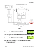


3. Installation 


The I/O unit is a battery-powered device therefore no power wiring is necessary. The 

units input and output connection details are shown in the attached diagram Figure 1. An 

installation drawing is also supplied P04242. The following paragraphs outline the 

installation in a step-by-step format. 


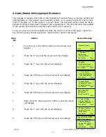
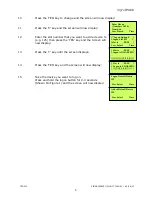
The unit should now be logged on to the system (see Input/Output Unit Logging on 

Procedure section). Note: If the unit is supplied with the system, it will already be logged 

onto the system. 


Remove the two lid retaining screws situated on the front cover. The front section of the 

unit can now be removed from the rear housing. 

Offer the unit up to the wall and using the back plate as a template mark out the three 

fixing holes. The unit can be fixed to the wall and all external wiring connections made. 


Connections to the hardwired input has to be wired using 4k7 and 2k2 resistors in a 

normally closed circuit. (See Figure 1) 4K7 is clear state, open circuit is fault and short 

circuit is fault.  When the 4k7 and 2k2 resistors are in series, (which makes 6K9) the I/O 

unit will send an alarm signal.  


The output is a standard clean contact, for switching voltage the output is rated 24v 1Ah 

DC.  


When all connections have been made and the unit has been logged on to the system 

the lid can be re-fixed. 

Содержание Signal point

Страница 1: ...INPUT OUTPUT UNIT INSTALLATION MANUAL ...

Страница 2: ...D012 SIGNALPOINT I O UNIT ISSUE 1 09 09 13 2 Table of Contents Section Page No 1 INTRODUCTION 3 2 I O UNIT POSITIONING 3 3 INSTALLATION 3 4 INPUT OUTPUT UNIT LOGGING ON PROCEDURE 4 5 TESTING THE SYSTEM 7 ...

Страница 3: ...radiators and air conditioning ducts will also adversely affect the performance of the system if they are too near the device 3 Installation The I O unit is a battery powered device therefore no power wiring is necessary The units input and output connection details are shown in the attached diagram Figure 1 An installation drawing is also supplied P04242 The following paragraphs outline the insta...

Страница 4: ... display 2 Press the 0 key and the screen will now display 3 Press the key until the screen displays 4 Press the YES key and the screen will now display 5 Press the key until the screen displays 6 Press the YES key and the screen will now display 7 Enter 221100 then press the YES key and the screen will display 8 Press the key until the screen displays 9 Press the YES key and the screen will now d...

Страница 5: ... 13 Press the key until the screen displays 14 Press the YES key and the screen will now display 15 Take the device you want to log on Press and hold the logon button for 2 3 seconds Shown On Figure 1 and the screen will now display Enter Device Numbers 1 256 Number Yes Finish Time Logon Options Logon Slot 125 Slot is FREE Yes Select Time Slot is FREE Logon is DISABLED Slot is FREE Logon is ENABLE...

Страница 6: ...ed to disabled once the logging on sequence has been completed 17 Press the NO key until the screen displays Note After logging the device on to the system there will be two faults 1st fault is processor reset 2nd fault is the Tamper Slot is IN USE Logon is DISABLED 01 FAULT TOT 02 Default Device 125 ZONE 01 DEVICE 125 Figure 1 ...

Страница 7: ...ure the correct alarm activation has been received The input should be cleared and the control panel reset The unit s output should then be activated and the relay checked to ensure it has changed state The device will light the front LED if the units relay is in the active state The output should then be de activated and the relay checked to ensure it has changed state The units relay can be acti...

Страница 8: ...oup co uk Dealer Information The information contained within this literature is correct at time of publishing The EMS Group reserves the right to change any information regarding products as part of its continual development enhancing new technology and reliability The EMS Group advises that any product literature issue numbers are checked with its head office prior to any formal specifications b...

Отзывы: