Empire Heating Systems DV210SGXLP-2 Скачать руководство пользователя страница 7

40946-0-1019

Page 7

SPECIFICATIONS

INTRODUCTION (CONT'D)

Model

DV-210

DV-215

Input BTU/HR (KW/H)

10,000 (2.9)

15,000 (4.4)

Height

21 3/8" (543mm)

24 7/8" (632mm)

Width

16 1/4 (413mm)

20 1/4" (514mm)

Depth

9 3/8" (239mm)

9 3/8" (239mm)

Gas Inlet

1/2" (13mm)

1/2" (13mm)

OPTIONS FOR ABOVE FURNACES

Blower

DVB-1

DVB-1

VINYL SIDING VENT KITS

Description

Model Number

Vinyl Siding Vent Kit

DV822

DV822

Vinyl Siding Vent Kit

VSK1

VSK1

VENT EXTENSION KITS

Part Number

Description

Used On

TH358

Vent Extension Kit For Propane 

Units (13"-19" Walls)

DV215SGXLP-1,2

TH357

Vent Extension Kit For Natural 

Units (13"-19" Walls)

DV215SGXNAT-1,2

TH345 & TH346

Vent Extension (13"-19" Walls)

DV210SGXNAT-2    DV210SGXLP-2

CONVERSION KITS

Part Number

Description

Used On

17081

Propane to Natural

DV210SGXLP

17080

Natural to Propane

DV210SGXNAT

17083

Propane to Natural

DV215SGXLP

17082

Natural to Propane

DV215SGXNAT

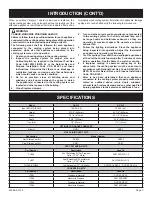
When an existing Category 1 heater is removed or replaced, the 

original venting system may no longer be sized to properly vent the 

attached appliances. Instructions shall also indicate effects of an 

improperly sized venting system (formation of condensate, leakage, 

spillage, etc.) and shall specify the following test procedure:


 WARNING

CARBON MONOXIDE POISONING HAZARD

Failure to follow the steps outlined below for each appliance 

connected to the venting system being placed into operation 

could result in carbon monoxide poisoning or death.

The following steps shall be followed for each appliance 

connected to the venting system being placed into 

operation, while all other appliances connected to the 

venting system are not in operation:

1.  Seal any unused openings in the venting system.

2.  Inspect the venting system for proper size and 

horizontal pitch, as required in the National Fuel Gas 

Code, ANSI Z223.1/NFPA 54 or the Natural Gas and 

Propane Installation Code, CSA B149.1 and these 

instructions. Determine that there is no blockage or 

restriction,  leakage,  corrosion  and  other  deficiencies 

which could cause an unsafe condition.

3.  As far as practical, close all building doors and 

windows and all doors between the space in which 

the appliance(s) connected to the venting system are 

located and other spaces of the building.

4. 

Close fireplace dampers.

5.  Turn on clothes dryers and any appliance not connected 

to the venting system. Turn on any exhaust fans, such 

as range hoods and bathroom exhausts, so they are 

operating at maximum speed. Do operate a summer 

exhaust fan.

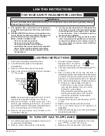
6.  Follow the lighting instructions. Place the appliance 

being inspected into operation. Adjust the thermostat 

so appliance is operating continuously.

7. 

Test for spillage from draft hood equipped appliances 

at the draft hood relief opening after 5 minutes of main 

burner operation. Use the flame of a match or candle.

8.  If improper venting is observed during any of the 

above tests, the venting system must be corrected in 

accordance with National Fuel Gas Code, ANSI Z223.1/

NFPA 54 and/or Natural Gas and Propane Installation 

Code, CSA B149.1.

9.  After is has been determined that each appliance 

connected to the venting system properly vents when 

tested as outlined above, return doors, windows, 

exhaust fans, fireplace dampers and any other gas-fired 

burning appliance to their previous conditions of use.

Содержание DV210SGXLP-2

Страница 1: ...try to light any appliance Do not touch any electrical switch do not use any phone in your building Leave the building immediately Immediately call your gas supplier from a neighbor s phone Follow the...

Страница 2: ...Specifications 6 Gas Supply 7 Clearances 8 Installation Instructions 8 9 Lighting Instructions 10 Maintenance 12 Pilot Flame Characteristics 13 Main Burner Flame Characteristics 13 Troubleshooting 13...

Страница 3: ...a qualified service person More frequent cleaning may be required due to ex cessive lint from carpeting bedding materials etc It is imperative that control compartments burners and circulating air pas...

Страница 4: ...adsorb or absorb onto or into walls masonry and other materials and fabrics in a room That will take some of the odorant out of the gas reducing its odor intensity Propane Gas may stratify in a closed...

Страница 5: ...ide detector as required in accordance with the above provisions shall comply with NFPA 720 and be ANSI UL 2034 listed and IAS certified 3 SIGNAGE A metal or plastic identification plate shall be per...

Страница 6: ...g of equipment shall be performed only by a qualified agency The term qualified agency means any individual firm corporation or company which either in personorthrougharepresentativeisengagedinandisre...

Страница 7: ...n while all other appliances connected to the venting system are not in operation 1 Seal any unused openings in the venting system 2 Inspect the venting system for proper size and horizontal pitch as...

Страница 8: ...test should be made Never use an exposed flame to check for leaks Appliance must be disconnected from piping at inlet of control valve and pipe capped or plugged for pressure test Never pressure test...

Страница 9: ...m screw provided On sheet rock wall secure furnace support bracket with 1 toggle bolt provided 64mm 13mm Figure 4 INSTALLATION INSTRUCTIONS 1 In selecting a location for installation it is necessary t...

Страница 10: ...side wall plate Use additional caulking to correct uneven wall surface such as clapboard 3 Attach 5 127mm diameter air inlet tube onto the collar of air drop assembly Attach caulked outside wall plate...

Страница 11: ...ockwise to ON 12 Replace control access panel front panel 13 Turn on all electric power to the appliance if applicable 14 CAUTION Pilot access cover must be kept tightly closed during operation TO TUR...

Страница 12: ...orifice threads when replaced 5 To remove the entire gas valve the nut holding the orifice fitting to the chamber must be removed and the gas supply to the valve disconnected After this the valve and...

Страница 13: ...Replace 3 Yellow pilot flame a Obstruction at pilot orifice b Clean and properly size orifice 4 Pilot and main burner go out during normal operation a Check millivolts b Check for proper size of pilot...

Страница 14: ...P8658 BURNER ORIFICE DV215 PROPANE 13 P104 ORIFICE FITTING 14 R1055 ELECTRODE AND WIRE 15 R12797 MANIFOLD 16 R12791 GAS VALVE 7000 MVRLC NATURAL 16 R12792 GAS VALVE 7000 MVRLC PROPANE 17 R12795 PILOT...

Страница 15: ...40946 0 1019 Page 15 MODEL DV 210 SHOWN 1 2 3 4 5 6 7 8 9 10 13 12 17 11 18 19 14 15 21 20 16 22 23 25 24 26 27 31 28 29 30 PARTS VIEW MODEL DV 210 SHOWN...

Страница 16: ...bsence of local codes with the National Electrical Code ANSI NFPA 70 or Canadian Electrical Code CSA C22 1 if an external electrical source is utilized This appliance is equipped with a three prong gr...

Страница 17: ...l Furnaces DV210 and DV215 OPTIONAL BLOWER INSTALLATION INSTRUCTIONS Oiling the Motor Oiling holes are provided on each end of the motor for oiling The blower should have five drops of 20 motor oil ev...

Страница 18: ...se and can be ordered by your Service Person or Dealer Proof of purchase is required for warranty parts All parts listed in the Parts List have a Part Number When ordering parts first obtain the Model...

Страница 19: ...le cancelled check or payment record should be kept to verify purchase date and establish warranty period Ready access to the appliance for service What Is Not Covered Damages that might result from t...

Страница 20: ...ww empirecomfort com Empire Comfort Systems Inc Belleville IL If you have a general question about our products please e mail us at info empirecomfort com If you have a service or repair question plea...

Страница 21: ...endido 9 DV 781 Ensamblaje Cubierta Agujero Encendido 10 DV 064 L mina Cubierta Agujero Encendido 11 852098 Tuerca para Tenedor Inyector 12 742134 Inyector Quemador DV 210 Natural 12 742133 Inyector Q...

Страница 22: ...40946 0 1019 Page 17 VISTA DE PARTES MODEL DV 210 SHOWN 1 2 3 4 5 6 7 8 9 10 13 12 17 11 18 19 14 15 21 20 16 22 23 25 24 26 27 31 28 29 30 MODELO DV 210 MOSTRADO...

Страница 23: ...ran los c digos locales de protecci n CUIDADO Marque todos los cables antes de la conexi n cuando le d servicio a los controles Errores atribuidos a conexi n de cables pueden causar una operaci n inco...

Страница 24: ...con el artefacto Se debe conservar un comprobante de venta un cheque cancelado o un registro de pago para verificar la fecha de compra y establecer el per odo de garant a Acceso f cil al artefacto par...

Страница 25: ...Comfort Systems Inc Belleville Illinois Si Ud tiene una pregunta general acerca de nuestros productos por favor env enos un correo al info empirecomfort com Si Ud tiene una pregunta de servicio o de r...

Отзывы: