


FG10099-3-0214
Page 10
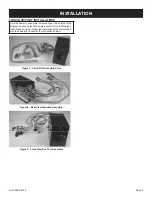
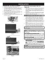
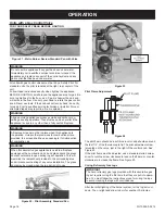
STANDARD PAN - VALVE/PILOT ASSEMBLY
1. Assemble the valve/pilot kit. See Figures 3 to 5.
2. Noting the distance between the grate tines, place the pilot
mounting bracket on the rear of the burner pan between
three to four inches from the right hand side of the burner
pan. See Figures 6 to 8.
3. Mark the location of the pilot bracket mounting hole.
4. Drill a 1/8” hole at this location. Or secure the bracket with a
self-tapping sheet metal screw. See Figures 6 to 8.
5. Mount the pilot. See Figures 7 and 8.
6. Attach the 3/8” stainless steel flex line from the valve to the
burner. See Figure 9.
Figure 6
Figure 7
Figure 8
Figure 9
INSTALLATION
INSTALLING THE APPLIANCE INTO THE
FIREPLACE
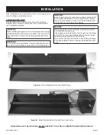
1. Place the Metro burner pan assembly into the fireplace (unit
is packaged as a match-throw, single burner assembly. The
valve, pilot and gas train must be assembled.). The unit
should be centered from both side to side and front to back.
See Figure 2.
2. Bend a 3/8” gas line with two 3/8” brass female flare fittings
(included on some models) to facilitate the gas connection
between the burner and the gas stub.
CAUTION:
Gas lines are easily kinked if bent too sharply.
3. Using an adjustable wrench, and turning in a clockwise
direction, attach a 1/2” female flare x 3/8” male flare brass
reducer fitting (included on some models) to the gas stub.
4. Using two adjustable wrenches, and turning in a clockwise
directions, attach one end of the gas line to the brass re-
ducer fitting installed in the previous step (one wrench on the
brass gas line fitting, and one wrench on the brass reducer
fitting).
5. Using two adjustable wrenches, and turning in a clockwise
direction, attach the other end of the gas line to the brass
fitting on the burner (one wrench on the gas line fitting, and
one wrench on the brass fitting on the valve assembly).
CAUTION:
Make sure all gas connections are snug but DO
NOT over tighten!
STOP! IT IS OUR RECOMMENDATION TO LIGHT THE PILOT
AND TEST THE IGNITION BEFORE ATTEMPTING TO SET
UP THE LOGS.
FOR UNITS WITH GAS CONTROL VALVES:
SEE “UNITS
WITH REMOTE SYSTEMS” SECTION ON PAGE 11 AND
“LIGHTING INSTRUCTIONS WITH SAFETY PILOT ON PAGE
15 BEFORE CONTINUING ON WITH THE INSTRUCTIONS
FOR MATCH THROW UNITS:
THIS IS NOT NECESSARY.
ONCE YOU HAVE COMPLETED THE STEPS IN THIS SEC-
TION, CONTINUE ON TO “FINAL SET UP ON PAGE 13.
6.
CHECK FOR LEAKS!
Apply soapy water to each connection
and watch for bubbles. If bubbles are seen, turn off the gas
supply, retighten the connections and
CHECK AGAIN. DO
NOT
use a lighted match or other source of ignition to check
for leaks. Repeat this procedure until you are sure that there
are no leaks. Proceed to “FINAL SET UP on page 13.
WARNING
DO NOT use sand in Liquid Propane Hearth Kits. Use the
Vermiculite, provided with the Liquid Propane Change Kit.
Содержание METRO BMHK-18N-1
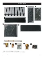
Страница 21: ...FG10099 3 0214 Page 21 PARTS VIEW...


