background image


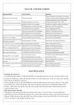
        FAULTS AND SOLUTIONS  


MAINTENANCE 

Cleaning of connectors 


The optical output interface of this series OTDR is a replaceable universal interface, and the end face must 
be kept clean during use. When the instrument fails to test the normal curve or the test result is not accurate, 
first consider cleaning the connector.  
When cleaning, be sure to turn off OTDR and visible red light fault location function. Screw off the output 
port and wipe the connection end face with a special dust-free paper towel or cotton swab wetted with 
alcohol.  At the same time, please cover the dust cap after using the instrument, and keep the dust-proof 
clean at the same time. 


Instrument screen cleaning 


The display of this series of optical time domain reflectors is 4.3 inch TFT full view color LCD with 
capacitive touch screen. When using, do not click on the LCD with sharp objects, or the LCD screen may be 
damaged. When cleaning, clean the LCD screen with soft paper. Do not wipe the LCD screen with organic 
solvent, otherwise it may damage the LCD screen.


Содержание EasySplicer OTDR

Страница 1: ...to 300m EasySplicer EasySplicer EasySplicer EasySplicer O O O OTDR TDR TDR TDR Owners Manual Professional instrument for measuring loss and finding faults in Fiber networks Domain Reflectometer Measu...

Страница 2: ...TDR LIST 8 EXPERT OTDR Expert Mode 9 OTDR SETTING 10 OTDR FILE SAVE FILES 11 OTDR FILE OPERATION File maintenance 12 EVENT MAP 13 LASER SOURCE 14 OPM OPTICAL POWER METER 15 VFL VISUAL FAULT LOCATOR 16...

Страница 3: ...ndinavia AB tries to make the user manual complete and accurate it may contain mistakes and the user uses it solely at his or her own risk EasySplicer OTDR components The following components are incl...

Страница 4: ...BRIEF FUNCTION KEYS...

Страница 5: ...MAIN MENU Start up Turn ON the instrument and the EasySplicer OTDR will start up in the Main menu Touch the function of Your choice...

Страница 6: ...eration functions Screen capture Capture the current interface the picture will be automatically saved in the instrument and the file name is the time when the screenshot is generated Note The laser r...

Страница 7: ...IOR and test time Pass Fail settings Avg Loss Thre set the threshold of the max link loss margin Event Loss Thre set the loss threshold of events in the link If it is greater than this threshold it wi...

Страница 8: ...ber of events passed numbers failed numbers In the event list NO the order of the current event Type the type of the current event Dis the distance of the current event Loss the loss value of the curr...

Страница 9: ...utoTest RealTest Avg Test Wavelength select the test wavelength of OTDR Test range usually choose about 2 times of the length of the optical fiber to be tested Test pulse width 3ns 20000ns optional di...

Страница 10: ...loss threshold of connection point fusion point in the link that can be tested between 0 2dB 30dB and the default value is 0 2dB Loss value larger than the setting value will be listed in the event li...

Страница 11: ...and press Enter to save the file If the automatic save otdr function is turned on System Settings it will be saved automatically after the test is complete without manual operation Auto save function...

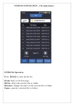
Страница 12: ...aintenance OTDR File Operation Press Files to enter the file list Head back to the first page Delete delete the current file or folder Rename change the name of the current file or folder Open open th...

Страница 13: ...ent point and the position of breakpoint can be displayed in a graphical form The result is clear and easy to understand The starting point Starting point with launch cable Connected gadgets causing l...

Страница 14: ...ive devices and wavelength responsiveness of detectors Open turn on the laser source Wave switch the wavelength the output wavelength is consistent with OTDR Mode switch the modulation frequency of li...

Страница 15: ...70 330 1000 2000Hz optical signal Wave switch the working wavelength Reference set current power as reference power CAL enter the user calibration mode and calibrate with the standard light source TWI...

Страница 16: ...sured fiber It is suitable for the detection of bare optical fibers jumpers and other high loss sections caused by near end faults and micro bending of optical fibers and cables which can leak red lig...

Страница 17: ...are as follows 1 First connect the LS and opm optical interface with standard jumpers Press Open and press Reference after the power is stable 2 Then connect the tested part to LS and opm optical int...

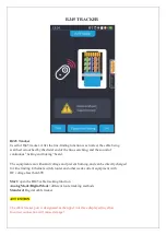
Страница 18: ...can withstand voltage and prevent burning and can be directly charged for line finding Ethernet switch router and other weak current equipment with DC voltage less than 60V Start open the RJ45 cable...

Страница 19: ...ote module when measuring Standard select different network cable standards Test start cable sequence test Exit exit the cable sequence test and return to the main interface WARNING Please do not test...

Страница 20: ...ch different units CAL adjust the test result according to the actual length and display length last test result correction Test start cable length test WARNING Please do not test online ATTENTION The...

Страница 21: ...ion Date Time set the instrument date and time Sound turn the touch tone on or off Flashlight turn the flashlight on or off USB connection connect to the computer after opening and transfer data Bluet...

Страница 22: ...output port and wipe the connection end face with a special dust free paper towel or cotton swab wetted with alcohol At the same time please cover the dust cap after using the instrument and keep the...

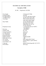
Страница 23: ...50ns 80ns 160ns 320ns 500ns 800ns 1us 2us 3us 5us 8us 10us 20us Ranging Accuracy 1m Sample interval 0 005 Test distance Linearity 0 05dB dB Sample Points 6k 128k Sample Resolution 0 05m 8m Loss Resol...

Отзывы: