026-1206 Rev 3 13-DEC-2012
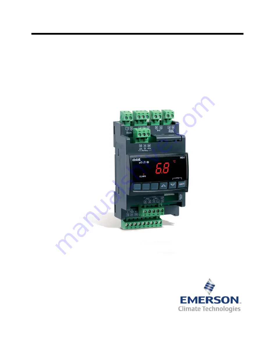
XEV22D Driver for Stepper
Electronic Expansion Valves Installation
and Operation Manual
Страница 1: ...026 1206 Rev 3 13 DEC 2012 XEV22D Driver for Stepper Electronic Expansion Valves Installation and Operation Manual ...
Страница 2: ......
Страница 3: ...Emerson Climate Technologies Retail Solutions 1065 Big Shanty Road NW Suite 100 Kennesaw GA 30144 USA Phone 770 425 2724 Fax 770 425 9319 ...
Страница 4: ......
Страница 5: ...NEL 9 8 1 KEYS AND FUNCTIONS 9 8 2 XEV22D LEDS 9 9 USER INTERFACE 10 9 1 TO SEE THE READ ONLY VALUES 10 9 2 TO SEE THE SETPOINT 10 9 3 TO MODIFY THE SETPOINT 10 9 4 TO ENTER PR1 PARAMETERS LIST 10 9 5 TO ENTER PR2 PARAMETERS LIST 10 9 6 TO MODIFY THE PARAMETERS VALUE 10 9 7 HOW TO ASSIGN A MODBUS ADDRESS 11 10 PARAMETERS 12 11 DIGITAL INPUTS 17 12 FORCED OPENING 17 13 ELECTRICAL CONNECTIONS 17 13 ...
Страница 6: ...DBUS NETWORKING TO E2S 22 19 1 COM PORT ASSOCIATIONS E2 VERSIONS 3 XX AND BELOW 22 19 2 COM PORT ASSOCIATIONS E2 VERSIONS 4 2 AND ABOVE 23 19 3 E2 SETUP OF DEVICES 23 19 3 1 Set Up Network Ports 23 19 3 2 Add and Connect the Device 23 19 4 WIRING TYPES 25 19 5 MODBUS TERMINATION BLOCKS 25 20 STANDARD VALUES 26 ...
Страница 7: ...r Emerson monitoring and supervising systems 2 2 Ordering Code CAUTION This manual is part of the product and should be kept near the controller for easy and quick reference The controller should not be used for purposes different from those described in this manual It can not be used as a safety device Check the application limits before proceeding SAFETY PRECAUTIONS AND WARNINGS Check that the s...
Страница 8: ... shows how the device takes the request of cooling See Figure 3 2 for wiring The First Level indicates the connections on the floor of the 4 DIN module and Second Level indicates the connections on the first floor that are only for the stepper motor of the valve and for the Hot Key Figure 3 1 How XEV22D Acts on Cooling Request Figure 3 2 XEV22D Wiring Connections ...
Страница 9: ... Retail Solutions P N 035 0002 BELDEN 8641 24 2 SHIELDED Retail Solutions P N 135 8641 PRESSURE TRANSDUCER BELDEN 8771 22 3 SHIELDED Retail Solutions P N 135 8771 8771 for alternate 600v rated wire use BELDEN 8618 16 AWG STEPPER VALVE Use valve manufacturer s harness with a maximum length not to exceed 30 feet 10 meters POWER LOADS AND VALVE Allow a maximum wire size of 14 AWG 2 mm2 Table 4 1 Wiri...
Страница 10: ... of a package unit is acceptable 5 1 Installation The XEV22D uses a DIN mount installation 5 2 Powering the XEV22D Retail Solutions supplies a wide variety of 24VAC transformers with varying sizes without center taps Table 5 2 shows the transformer sizes and are non center tapped 5 2 1 Choosing Transformer Sizes The transformer used to power the XEV22D should have at least a 20VA rating The XEV22D...
Страница 11: ...d In most cases the distance between the XEV22D and the transformer that sup plies power to it is not enough to be of concern how ever it is very important NOT to exceed this maximum wire length or the controller will not oper ate correctly Use these formulas to determine if the wire gauge you are using fits within specification Sensors requiring 24VAC should not be powered from the same transform...
Страница 12: ...he tEP parameter table reported below tEP Model LSt steps 10 uSt steps 10 CPP mA 10 CHd mA 10 Sr step s 0 Manual settings Par Par Par Par Par 1 Alco EX4 EX5 EX6 5 75 50 10 500 2 Alco EX7 10 160 75 25 500 3 Alco EX8 500 10 260 80 50 500 4 Danfoss ETS 25 50 7 262 10 10 300 5 Danfoss ETS 100 10 353 10 10 300 6 Danfoss ETS 250 400 11 381 10 10 300 7 Sporlan SEI 0 5 11 0 159 16 5 200 8 Sporlan SER 1 5 ...
Страница 13: ...the Inductor Ex tender P N 335 3500 For a CPP parameter of 12 the measured current should be near 120 mA AC for a CPP setting of 16 the measured current should be near 160 mA AC Below is a description of using an AC current me ter to test a stepper valve Using an AC Volt meter to measure the voltage across a stepper valve will not produce accurate re sults if the valve is driven by a voltage chopp...
Страница 14: ...y repeating the above procedure on the Sporlan valve Green wire and XEV22D controller The in line AC mA meter is also compatible with the constant voltage stepper valve drivers used in the MultiFlex ESR CC100 and CCB 7 Absolute Maximum Power The XEV22D controller is capable of driving a wide range of stepper valves listed in Table 7 1 are the maximum values of current that the actuator can supply ...
Страница 15: ...ues of the probes In programming mode it slides the codes of the parameters or increases their val ues In programming mode it slides the codes of parameters or decreases their values Key Combinations Table 8 1 XEV22D Front Panel Keys and Functions To lock and unlock the keyboard To enter programming mode LED Mode Function ON Low pressure alarm ON Maximum operating pres sure alarm OFF Valve is comp...
Страница 16: ... Press SET to store the new value 9 4 To Enter Pr1 Parameters List To enter in Pr1 level menu 1 Press the SET DOWN arrow keys for about 3 sec onds 2 The device will display the first parameter in Pr1 menu 9 5 To Enter Pr2 Parameters List To enter to Pr2 parameters list 1 Enter the Pr1 level menu 2 Select Pr2 parameter and press SET 3 The PAS label will be displayed followed by a blinking 0 4 Inser...
Страница 17: ...ash 4 Use the arrow keys to set the 321 password Press SET to save 5 Use the arrow keys to scroll through and locate nod Press SET Use the arrow keys to scroll through and locate Std Press SET 6 Use the arrow keys to scroll through and locate Adr Press SET Use the arrow keys to choose the address number of the device Press SET to save 7 To exit press the SET and UP arrow keys together or wait 15 s...
Страница 18: ...lar valves bP 4 wires bipolar valves CAUTION By changing this parameter the valve has to be re initial ized tEP Predefined valve selection 0 to 13 If tEP 0 the user has to modify all the parameters of configuration in order to use the valve If tEP is different from 0 the controller performs a fast configuration of the following parameters LSt Ust Sr CPP and CHd To select the correct value refer to...
Страница 19: ... 100 Opening valve percentage when the start function is active and during post defrost phase This phase duration is SFd time SFd Start function duration 0 0 to 42 0 min tens of seconds It sets start function duration and post defrost duration During this phase the alarms are neglected Sti Stop regulation interval 0 0 to 24 0 hours tens of minutes After regulating continuously for Sti time the val...
Страница 20: ...ture probe PtM to ntC Sets the kind of probe used by the controller PtM Pt1000 ntC NTC probe otE Temperature probe calibration 12 0 to 12 0 C 21 to 21 F DIGITAL INPUTS i1P Digital input 1 free of voltage digital input polarity CL OP CL activated when closed OP activated when opened i1F Digital input 1 free of voltage digital input function CCL rL CCL cooling call rL digital input activates relay d...
Страница 21: ...n at the dML percentage every one second until LOP alarm is active MSH Maximum superheat alarm LSH to 32 0 C LSH to 176 F When the superheat exceeds this value a high superheat alarm is sig naled after interval SHd LSH Lowest superheat alarm 0 0 to MSH C 32 to MSH F When the superheat goes down to this value a low superheat alarm is signaled after interval SHd SHy Superheat alarm hysteresis 0 0 to...
Страница 22: ...the actual opening percentage of the valve d1S Free of voltage digital input state Read only Shows the free of voltage digital input d2S High voltage digital input state Read only Shows the high voltage digital input state Adr RS485 serial address 1 to 247 Identifies the controller address when connected to a MODBUS compat ible monitoring system Mod MODBUS AdU to StD AdU Only for XWEB systems In t...
Страница 23: ...bles have to be used Before connect ing the cables verify that the power supply complies with the controller s requirements Separate the probe cables from the power supply cables from the outputs and the power connections Do not exceed the maxi mum current allowed on each relay in case of heavier loads use a suitable external relay 13 1 Probes The recommended temperature probe placement is illustr...
Страница 24: ...programmed Hot Key into the 5 pin con nector and then turn the controller ON 3 Automatically the parameter list of the Hot Key is downloaded into the controller memory the doL message will blink followed by a flashing End LED 4 After 10 seconds the controller will restart work with the new parameters 5 Remove the Hot Key NOTE The Err message is displayed in case an error or failure in programming ...
Страница 25: ...nal memory is detected In this case call for service Message Cause Outputs nA None of the digital in puts configured as CCL are activated Valve closed Pf The PEd time is elapsed and the regu lation is stopped Valve closed after PEd There is a probe error P1 Temperature probe fault According to PEo and PEd P2 Pressure transducer fault According to PEo and PEd HSH High superheat alarm By PI LSH Low ...
Страница 26: ...n depending on the valve 20VA max Display Three 3 digits with icons red LEDs height 14 2 mm Inputs 1 temperature probe Pt1000 or NTC 1 pressure transducer 4 to 20mA or 0 to 5V Digital Inputs 1 free of voltage 1 at high voltage Outputs for Valve Bipolar or unipolar valves Data Storage On the non volatile memory EEPROM Kind of Action 1B Pollution Grade Normal Software Class A Temperature Operating 0...
Страница 27: ... the MODBUS cable to the RS485 terminals and connect the MODBUS shield to the pin 16 terminal Terminate the end of the MODBUS network at the last XEV22D device on the daisy chain with the MODBUS ter mination block P N 535 2711 or by connecting a 150 ohm resistor between the MODBUS terminals Figure 18 1 XEV22D to E2 Wiring Diagram E2 PIB version 3 xx and below shown in this example CAUTION For the ...
Страница 28: ...rson units Connect the MODBUS network cable to the three terminal connector on the COM port you wish to as sign as MODBUS Reverse polarity of on RS485 cable from E2 to the device COM ports can only be used for one function in other words if COM2 is set up as the I O network you cannot connect MODBUS devices to COM2 En sure your E2 is equipped with an RS485 COM Card P N 637 4890 and configured in E...
Страница 29: ...ction field for all COM ports on the E2 Highlight the COM port con nection field that will be used for the device and press LOOK UP From the list of network types select MODBUS 5 Four fields will become visible underneath the COM port connection field which pertain to the way the device communicates Baud Default setting is 19 2k The baud rate setting should be set to match the baud rate of the dev...
Страница 30: ... on this device to a different number that is not being used 7 Repeat Steps 5 and 6 until each device has a name and address 8 When finished press to return to the Net work Setup menu then press Network Sum mary Figure 19 8 Locate the devices you set up and look at each device s status in the Status field You will see one of the following messages Online The device is communicating normal ly Offli...
Страница 31: ... than or equal to 0 325 mm2 AWG22 19 5 MODBUS Termination Blocks Because the XEV22D device has no on board means of termination use the MODBUS termination block P N 535 2711 for termination that can be wired to the end of the cable segment using the three pin connector Wire the two signal wires to the out side terminals and connect the shield to pin 16 keep ing the exposed shield wire length as sh...
Страница 32: ...00 85 Pr2 SFd Start function duration 0 0 to 42 0 min tens of seconds 1 3 Pr2 Sti Stop regulation interval 0 0 to 24 0 hr tens of minutes 0 Pr2 Std Stop duration 0 to 60 min 0 Pr2 MnF Maximum opening percentage 0 to 100 100 Pr2 FOP Forced opening time out 0 to 100 not used not used Pr2 PI PARAMETERS For trained staff use only Pb Proportional band 0 1 to 50 0 C 1 to 90 F 10 0 Pr2 rS Band offset 12 ...
Страница 33: ...00 30 Pr2 MSH Maximum superheat alarm LSH to 32 0 C LSH to 176 F 80 0 Pr1 LSH Lowest superheat alarm 0 0 to MSH C 32 to MSH F 2 5 Pr1 SHy Superheat hysteresis 0 1 to 25 5 C 1 to 77 F 0 1 Pr2 SHd Superheat alarm activation delay 0 to 255 sec 120 Pr1 FrC Fast recovery constant 0 to 100 sec 50 Pr2 DISPLAY Lod Local display SH PEr P1 P2 SH Pr1 CF Temperature measurement units C F C Pr2 PMU Pressure me...
Страница 34: ......
Страница 35: ......
Страница 36: ...d or its affiliates collectively Emerson reserves the right to modify the designs or specifications of such products at any time without notice Emerson does not assume responsibility for the selection use or maintenance of any product Responsibility for proper selection use and maintenance of any product remains solely with the purchaser and end user 026 1206 13 DEC 2012 Emerson is a trademark of ...