


Safety
Information
Introduction
Product
information
System
design
Mechanical
installation
Electrical
installation
Getting
started
Optimisation
Parameters
Technical
data
Component
sizing
Diagnostics
32
Unidrive SP Regen Installation Guide
www.controltechniques.com Issue Number: 2
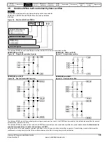
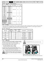
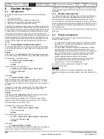
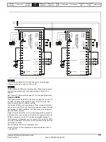
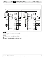
4.2.1 Single Regen, single / multiple motoring system
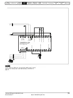
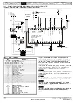
Figure 4-1 Power connections: Single Regen, single / multiple motoring system
Figure 4-1 shows both the power and control connections for the standard
regen solution this being a single regen and single motoring drive system.
For this solution the Vac supply is temporarily connected to the Regen
drive’s L1, L2, L3 inputs for initial power-up only, removing the need for
an external charging circuit. The main AC supply to L1, L2, L3 on the
Regen drive (K3) is interlocked with the Regen drive’s enable preventing
operation when the charging circuit is still connected.
The regen inductor duty is very arduous and therefore selection is critical
as a result only Regen inductors specified in this guide should be used.
U
V
W
-DC +DC
L1
L2
L3
-DC
+DC
21
1
2
3
4
5
6
7
8
9
10
11
41
42
22
23
24
25
26
27
28
29
30
31
T.30
T.24
L1
L2
RFI
K1
F1
F2
F3
VDR1
VDR2
VDR3
VDR4
VDR6
Tc.1
AC Supply
Power-up
Connections
AC Supply
Connections
Motoring
drive DC
Connections
+
2
4
outpu
t
E
nable
m
o
to
r
dri
ve
Co
nt
a
cto
r
clo
se
d
0c
om
m
o
n
Dr
iv
e
e
na
b
le
K2
Rly.1
(optional)
L1
L2
L3
PE
Aux.3
C1
OPD1
Aux.1
Regen drive
S1
Aux.1
K2
Aux.2a
Aux.2a
Reg
en indu
ctor
ther
mistor
0V
c
o
mm
o
n
V
V
Drive he
althy
Reset in
put
Aux.3
S6
C
ontactor
co
ntrol
VD
R
5
Vsupply
K3
Charging branch circuit
Aux.2b
K3
Vsupply
Aux.2b
Note: Surge suppressors to be fiited to contactor coils.
Supply
ground
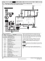
Table 4-1 Key to Figure 4-1
Key
Description
L1, L2, L3
Three phase supply
F1, F2, F3
Main regen system supply fuses
VDR1, VDR2, VDR3 Varistor network line-to-line
VDR4, VDR5, VDR6 Varistor network line-to-ground
RFI
Optional RFI Filter
C1
Switching frequency filter capacitor
L1
Switching frequency filter inductor
L2
Regen inductor
K1
Main supply switch or contactor
K2
Regen drive main contactor
K3
Charging contactor
OPD1
Overload protection device for C1
Aux.3
K3 NC auxiliary contact
Aux.2a
K2 NO auxiliary contact
Aux.2b
K2 NC auxiliary contact
Aux.1
OPD1 NO auxiliary contact
Rly.1
Optional isolation for enable between Regen and motoring drive
Mt.1
Motor thermistor
Tc.1
Regen inductor thermistor
Vsupply
System control supply
+DC, -DC
Motoring drive power connection to Regen drive
S1
Regen drive enable
S2
Motoring drive enable
S3
Motoring drive reset
S4
Motoring drive run forward
S5
Motoring drive run reverse
S6
Regen drive reset input (Pr
8.24
= Pr
10.33
)
Table 4-1 Key to Figure 4-1
Key
Description
NOTE
Содержание SP1201
Страница 219: ......
Страница 220: ...0471 0029 02 ...