background image

2

Physical installation

There are two types of power modules that will be discussed in this
document. They are the black power module (701PBK) and the green power
module (701PGN).

2.1

Installing Black power module (701PBK)

Prerequisites

Install the HART

®

 device according to standard installation practices and the

manufacturer’s instructions, being sure to use an approved thread sealant
on all connections.

Procedure

1. Unscrew the power module cover from the wireless device.
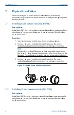
2. Connect the power module to the wireless device. The power

module has a keyed connection to prevent improper connection.

Note

Wireless devices should be powered up in order of proximity from
the Smart Wireless Gateway, beginning with the closest device to the
Gateway. This will result in a simpler and faster network installation.

3. Connect the power module to the wireless device. The power

module has a keyed connection to prevent improper connection.

Figure 2-1: Black Power Module Installation

2.2

Installing Green power module (701PGN)

Prerequisites

Install the HART device according to standard installation practices and the
manufacturer’s instructions, being sure to use an approved thread sealant
on all connections.

Quick Start Guide

August 2022

6

Emerson.com/Rosemount

Содержание SmartPower 701PBK

Страница 1: ...Quick Start Guide 00825 0100 4701 Rev DE August 2022 SmartPower Solutions ...

Страница 2: ...ctrical shock The power module may be replaced in a hazardous area The power module has surface resistivity greater than one gigaohm and must be properly installed in the wireless device enclosure Care must be taken during transportation to and from the point of installation to prevent electrostatic charge build up CAUTION Each Black Power Module contains two C size primary lithium thionyl chlorid...

Страница 3: ...ontents Warning on product labels 5 Physical installation 6 Verify operation 8 Disposal recycling of depleted power modules 11 Product Certifications 12 August 2022 Quick Start Guide Quick Start Guide 3 ...

Страница 4: ...Quick Start Guide August 2022 4 Emerson com Rosemount ...

Страница 5: ...ach label The text of the warning is WARNING Potential Static Hazard Use Caution when Handling Risk of Fire Explosion or Severe Burn Hazard DO NOT Recharge Disassemble Heat above 100 C Incinerate or Expose Contents to Water Li metal content approx 5g Figure 1 1 Warning Label on 701PBK Figure 1 2 Warning Label on 701PGN August 2022 Quick Start Guide Quick Start Guide 5 ...

Страница 6: ...he power module has a keyed connection to prevent improper connection Note Wireless devices should be powered up in order of proximity from the Smart Wireless Gateway beginning with the closest device to the Gateway This will result in a simpler and faster network installation 3 Connect the power module to the wireless device The power module has a keyed connection to prevent improper connection F...

Страница 7: ...ld be powered up in order of proximity from the Smart Wireless Gateway beginning with the closest device to the Gateway This will result in a simpler and faster network installation 3 Close the housing cover and tighten Ensure the power module cover is fully tightened to prevent moisture ingress The lip of the polymer power module cover should be in contact with the surface of the polymer enclosur...

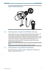
Страница 8: ...n using Field Communicator If you are able to communicate to the wireless device via a Field Communicator the power module is powering the device and working correctly Figure 3 1 shows how to connect a Field Communicator to a wireless device with either the black or green power module Figure 3 1 Connect to Device 1 2 3 4 5 6 7 8 0 9 A Communication terminals B Handheld communicator C HART modem Qu...

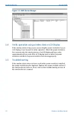
Страница 9: ...rk with the Smart Wireless Gateway s integrated web server open the Smart Wireless Gateway s integral web interface and navigate to the Explorer page If the wireless device has joined the network the power module is functioning properly Note It may take several minutes for the device to join the network 3 3 Verify operation using AMS Device Manager When the device has joined the network it will ap...

Страница 10: ...display will turn on for approximately 40 seconds If the LCD display turns on after the power module is installed the power module is functioning properly 3 5 Troubleshooting If the wireless device does not turn on after the power module is installed the power module may be depleted Replace the power module and see if the wireless device turns on If not refer to the troubleshooting section of the ...

Страница 11: ... regulations and requirements before shipping Handling considerations Each black power module contains two C size primary lithium batteries Each green power module contains one D size primary lithium battery Under normal conditions the battery materials are self contained and are not reactive as long as the batteries and the battery pack integrity are maintained Care should be taken to prevent the...

Страница 12: ...EC and the Canadian Electrical Code CEC permit the use of Division marked equipment in Zones and Zone marked equipment in Divisions The markings must be suitable for the area classification gas and temperature class This information is clearly defined in the respective codes 5 4 USA 5 4 1 KF USA Intrinsically Safe IS Certificate 3042016 Standards FM Class 3600 1998 FM Class 3610 2010 FM Class 3810...

Страница 13: ...F ATEX Intrinsic Safety Certificate Baseefa11ATEX0042X Standards EN 60079 0 2018 EN 60079 11 2012 Markings II 1 G Ex ia IIC T4 Ga T4 55 C Ta 70 C II 1 G Ex ia IIC T5 Ga T5 55 C Ta 40 C See Table 5 1 or Table 5 2 for parameters Special Condition for Safe Use X The plastic enclosure of the Model 701P SmartPower Power Modules may constitute a potential electrostatic ignition risk and caution should b...

Страница 14: ...Safety Certificate RU C US AЖ58 B 01628 21 Markings 0Ex ia IIC T4 T5 Ga X T4 55 C Ta 70 C T5 55 C Ta 40 C 5 9 INMETRO Brazil 5 9 1 KF Brazil Intrinsic Safety Certificate UL BR 14 0123X Standards ABNT NBR IEC 60079 0 2008 Errata 1 2011 ABNT NBR IEC 60079 11 2009 Markings Ex ia IIC T4 T5 Ga X T4 55 C Ta 70 C T5 55 C Ta 40 C 5 10 China 5 10 1 KF China 本质安全 证书 GYJ20 1357X CCC 认证 所用标准 GB3836 1 2010 GB3...

Страница 15: ...4 产品的安装 使用和维护应同时遵守产品使用说明书 GB3836 13 2013 爆炸性环境 第 13 部分 设备的修理 检修 修 复和改造 GB T3836 15 2017 爆炸性环境 第 15 部分 电气装置 的设计 选型和安装 GB T3836 16 2017 爆炸性环境 第 16 部 分 电气装置的检查与维护 GB T 3836 18 2017 爆炸性环境 第 18 部分 本质安全电气系统 GB50257 2014 电气装置安装工程 爆炸和火灾危险环境电力装置施工及验收规范 的有关规定 See Table 5 1 or Table 5 2 for parameters 5 10 2 Tables Table 5 1 701PBK Uo 7 8 V Io 2 16 A Po 0 83 W Co 3 0 µF Lo 7 6 µH August 2022 Quick Start Guid...

Страница 16: ...Table 5 2 701PGN Uo 3 9 V Io 2 78 A Po 2 71 W Co 100 µF Lo 4 6 µH Quick Start Guide August 2022 16 Emerson com Rosemount ...

Страница 17: ...5 11 Declaration of Conformity August 2022 Quick Start Guide Quick Start Guide 17 ...

Страница 18: ...rtificate Equipment Group II Category 1 G Ex ia IIC Ga T4 T5 Harmonized Standards EN 60079 0 2012 A11 2013 EN 60079 11 2012 ATEX Notified Body SGS FIMKO OY Notified Body Number 0598 Takomotie 8 00380 HELSINKI Finland ATEX Notified Body for Quality Assurance SGS FIMKO OY Notified Body Number 0598 Takomotie 8 00380 HELSINKI Finland Quick Start Guide August 2022 18 Emerson com Rosemount ...

Страница 19: ...SJ T11364Ⲵ㿴ᇊ㘼ࡦ This table is proposed in accordance with the provision of SJ T11364 O Ѫ䈕䜘ԦⲴᡰᴹ 䍘ᶀᯉѝ䈕ᴹᇣ 䍘Ⲵਜ਼䟿 վҾGB T 26572ᡰ㿴ᇊⲴ䲀䟿㾱 O Indicate that said hazardous substance in all of the homogeneous materials for this part is below the limit requirement of GB T 26572 X Ѫ 䈕䜘Ԧᡰ Ⲵᡰᴹ 䍘ᶀᯉ䟼ˈ㠣ቁᴹа 䍘ᶀᯉѝ䈕ᴹᇣ 䍘Ⲵਜ਼䟿儈ҾGB T 26572ᡰ㿴ᇊⲴ䲀䟿㾱 X Indicate that said hazardous substance contained in at least one of the homogene...

Страница 20: ...on com 2022 Emerson All rights reserved Emerson Terms and Conditions of Sale are available upon request The Emerson logo is a trademark and service mark of Emerson Electric Co Rosemount is a mark of one of the Emerson family of companies All other marks are the property of their respective owners ...

Отзывы: