background image

Emerson Process Management
00375-0047-0001, rev F

Emerson Process Management

Asset Optimization Division

12001 Technology Drive

Eden Prairie, MN 55344   USA 

www.fieldcommunicator.com

©2009, Emerson Process Management.
The contents of this publication are presented for 
informational purposes only, and while every effort 
has been made to ensure their accuracy, they are 
not to be construed as warranties or guarantees, 
express or implied, regarding the products or 
services described herein or their use or applicability. 
All sales are governed by our terms and conditions,
which are available on request. We reserve the right 
to modify or improve the designs or specifications 
of our products at any time without notice.
All rights reserved. The Emerson logo is a trademark 
and service mark of Emerson Electric Co. All other
marks are the property of their respective owners.
Printed in USA/2-2009

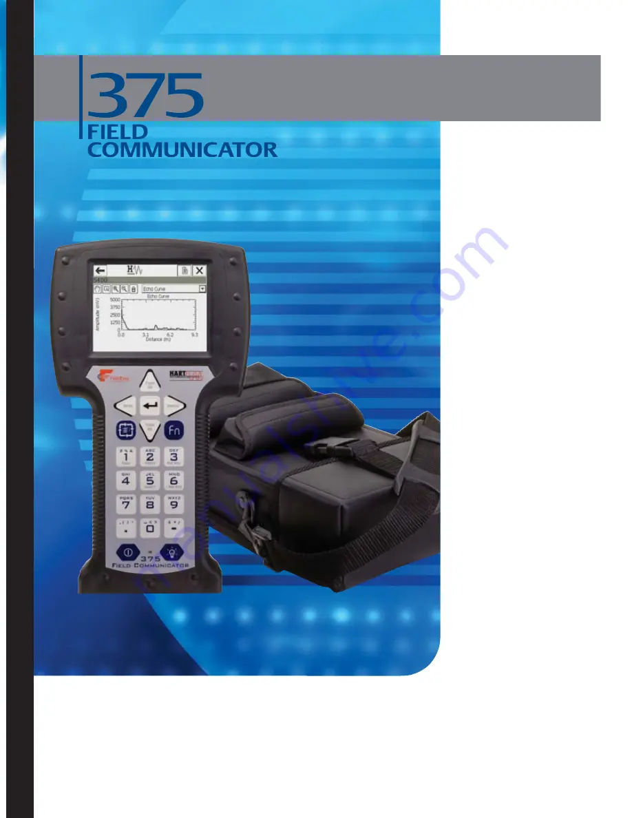
USER’S

MANUAL

3

7

5

 F

ield
 Com

m

u

n

ic

a

tor

 U

ser

’s M

an

u

a

l

Содержание Rosemount 375

Страница 1: ...USER S MANUAL 375 Field Communicator User s Manual ...

Страница 2: ......

Страница 3: ...rademark of the Infrared Data Association FOUNDATION is a trademark of the Fieldbus Foundation HART is a registered trademark of the HART Communication Foundation WirelessHART is a trademark of the HART Communication Foundation Hitachi is a registered trademark of Hitachi America Ltd All other marks are the property of their respective owners US and foreign patent numbers are pending NOTICE Read t...

Страница 4: ......

Страница 5: ...ining 2 5 Charge the Battery 2 5 Maintaining the Battery Life and Performance 2 7 Installing the System Card and the Battery 2 8 Removing the Battery and the System Card 2 9 Starting Up and Shutting Down 2 9 Starting the 375 Field Communicator 2 9 Entering Stand By 2 10 Shutting Down the 375 Field Communicator 2 10 Basic Features and Functions 2 11 Using the Keypad 2 12 Using the Touch Screen 2 14...

Страница 6: ...splaying the Online Menu 3 11 Saving an Online Device Configuration 3 12 Displaying the Device Setup Submenu 3 12 Displaying Graphics 3 14 Using Hot Keys 3 15 Setting up Hot Key Options 3 15 Executing a Hot Key Option 3 16 Removing a Hot Key Option 3 16 Removing all Hot Key Options 3 16 Configuring the HART Application 3 17 Changing the HART Polling Option 3 17 Changing Ignored Status Messages 3 1...

Страница 7: ...Displaying Graphics 4 20 Configuring the Fieldbus Application 4 21 Changing the Fieldbus Polling Addresses 4 21 Changing the Slot Time 4 21 Viewing Available Device Descriptions 4 22 Running Fieldbus Diagnostics 4 23 DC Voltage and Noise Level Measurement 4 23 Signal Level Measurement 4 23 Disconnecting from a Fieldbus Device 4 24 SECTION 5 Troubleshooting Overview 5 1 Troubleshooting Suggestions ...

Страница 8: ...ng Locations B 1 European Directive Information B 1 Hazardous Locations Certifications KL option only B 2 International Certifications B 2 North American Certifications B 2 European Certifications B 3 Power Supply Charger Certification B 4 Label Drawings B 4 Approval Drawings B 7 APPENDIX C Graphics Information Overview C 1 Screen Layout C 2 Buttons C 3 Graphics Options C 4 Images C 4 Charts C 5 G...

Страница 9: ...on with connected HART devices and viewing the menus Section 4 Fieldbus Functionality contains information on starting and configuring the Fieldbus Application establishing communication with connected fieldbus devices and viewing the menus Section 5 Troubleshooting provides solutions to the most common 375 Field Communicator operating problems Appendix A Reference Information provides physical fu...

Страница 10: ...Introduction 1 2 ...

Страница 11: ...icated by a warning symbol Refer to the following safety messages before performing an operation preceded by this symbol See the Troubleshooting section for more warning messages IMPORTANT NOTICE Ensure the battery and the 375 Field Communicator are properly aligned during assembly to prevent damage to the connector pins IMPORTANT NOTICE Do not pull up on the battery because this can damage the co...

Страница 12: ...inal is a positive connection for its protocol while the black terminal is a common terminal shared by both protocols An access door ensures only one pair of terminals is exposed at any one time Several markings indicate which pair of terminals is for which protocol The infrared port and card reader let the 375 Field Communicator or its System Card interface with a PC Use the keypad or touch scree...

Страница 13: ...he IS approval and the warranty Working in an Intrinsically Safe IS Area An IS approved 375 Field Communicator can be used in Zone 0 FM and CSA only Zone 1 or Zone 2 Division 1 and Division 2 locations KL option only An IS approved 375 Field Communicator may be connected to loops or segments that are attached to equipment located in Zone 0 Zone 1 Zone 2 Zone 20 Zone 21 Zone 22 Division 1 and Divis...

Страница 14: ... using the battery or power supply charger 00375 0003 0005 understand and follow the guidelines below When transporting a Li Ion Power Module follow all applicable regulations Use the power supply charger with the 375 Field Communicator only Use only the supported power supply charger to charge the battery Failure to comply may permanently damage your 375 Field Communicator and will void the IS ap...

Страница 15: ... The previous 4 pin power supply charger is incompatible with the 6 pin Li Ion Power Module Prior to first portable use fully charge the battery The battery can be charged separately or while attached to the 375 Field Communicator The 375 is fully operable when the battery is recharging The power supply charger can remain connected after the battery is fully charged An overcharge condition will no...

Страница 16: ...lug the power supply charger into a power outlet 2 Ensure the connectors match before connecting the power supply charger to the battery 3 Plug the power supply charger connector into the battery The battery is fully charged when the light on the power supply charger is green NiMH Adapter Cable Lights Power supply charger Green connector on the power supply charger ...

Страница 17: ...tures can reduce performance Ensure the remaining charge level is at or near mid capacity when storing for an extended time The remaining charge will slowly drain during storage Periodically charge the Power Module to ensure the remaining charge does not drain to low levels NiMH Battery Packs Recharge the Battery Pack when it is nearly discharged NiMH Battery Packs benefit from full discharge and ...

Страница 18: ...4 With the 375 Field Communicator still face down ensure the tops of the two battery retaining screws are flush with the top of the 375 Install the battery by aligning the sides of the battery and the 375 and carefully sliding it forward until it is secure 5 Carefully hand tighten the two battery retaining screws to secure the battery Do not over tighten 0 5Nm maximum torque load The tops of the s...

Страница 19: ...rger Overview on page 2 4 for details on charging the battery Before operating the 375 Field Communicator ensure The 375 Field Communicator is not damaged The battery is fully seated All screws are sufficiently tightened An Expansion Module or Expansion Port Plug is in place The Communication Terminal recess is free of dirt and debris Starting the 375 Field Communicator Press and hold the On Off k...

Страница 20: ...turn to the application The multifunction LED will slowly flash a green light when the 375 Field Communicator is in stand by To leave stand by press the On Off key The 375 Field Communicator also enters stand by if the stand by timer has expired See Power Status on page 2 18 for more information Shutting Down the 375 Field Communicator To shut down the 375 Field Communicator press the On Off key F...

Страница 21: ...r arrow keys HART and FOUNDATION fieldbus Communication Terminals top Expansion Port side Enter key Function key for multiple key combination functionality Alphanumeric keypad On Off key Backlight Adjustment key Powersupply charger connector side on the battery colored green for Li Ion Power Modules or black for NiMH Battery Packs Battery back and System Card internal Stylus back ...

Страница 22: ...y is disabled when the 375 Field Communicator is in Listen For PC mode or when ScratchPad is open Arrow Navigation keys Four arrow navigation keys let you move through the menus in the applications Press the right arrow key to select menu items and to move into the menu Enter key The Enter key lets you select the focused highlighted item or complete an editing action For example if you push the En...

Страница 23: ...tensity of the display There are four different settings The intensity impacts the charge in the battery Expect a shorter charge life for higher intensities see Backlight on page 2 16 for the settings Function key The Function key lets you enable alternate functionality on select keys The grey characters on the keys indicate the alternate functionality When the Function key is enabled the orange M...

Страница 24: ...of the touch screen display Repair of the touch screen requires replacement of the entire 375 Field Communicator display assembly which is possible only at an authorized service center Use the back arrow icon to return to the previous menu Use the terminate icon in the upper right corner of the touch screen to end the application Use the Soft Input Panel SIP keyboard The SIP keyboard allows for al...

Страница 25: ...cation automatically polls for devices See Section 3 HART Functionality for more information Starting the Fieldbus Application From the 375 Main Menu double tap FOUNDATION Fieldbus Application to run the Fieldbus Application See Section 4 Fieldbus Functionality for more information Running the Settings Menu From the 375 Main Menu double tap Settings to view the Settings menu This menu lets you set...

Страница 26: ...eld Communicator must be running on external power when the RE IMAGE operation is performed During the operation the stand by and auto off timers are disabled This operation should only be performed under the direction of Technical Support personnel Tap OK to return to the Settings menu Backlight The Backlight setting lets you adjust the intensity of the screen To adjust the backlight drag the sli...

Страница 27: ...lider When you find an appropriate contrast setting tap OK to retain this setting for this session only SET DEFAULT to retain this setting upon start up or CANCEL to exit without changes NOTE Temperature can affect contrast License The License setting lets you view the enabled licenses on the System Card The HART Application license is standard in every 375 Field Communicator Other licenses availa...

Страница 28: ...e Power Savings option conserves additional power by letting the 375 Field Communicator enter stand by or shut down when communicating with a device To enable Maximize Power Savings tap the checkbox and a checkmark appears If this option is disabled the 375 Field Communicator will not enter stand by or shut down when communicating with a device The Maximize Power Savings option applies only when t...

Страница 29: ... restored After the battery is discharged make sure it is fully recharged before using it without the power supply charger You can use the 375 Field Communicator while the battery is recharging To retrain the battery 1 Disconnect the power supply charger if it is connected to the 375 Field Communicator 2 Double tap Retrain The Battery from the Settings menu 3 Wait until the 375 Field Communicator ...

Страница 30: ...button is highlighted black when selected To delete an event capture tap the DELETE EVENT FILE button NOTE While event capture is enabled device warning messages do not appear To create and send an event capture file to Technical Support personnel 1 Enable event captures and tap OK 2 Start the HART Application 3 Enter a file name for the event capture file and tap OK The file is saved to a default...

Страница 31: ... Secure Digital card reader Insert the 375 System Card into a card reader and system software upgrades and device descriptions can be sent to the System Card using the Easy Upgrade Programming Utility Your System Card must be licensed for the Easy Upgrade option to download system software and device descriptions to it A supported card reader may be required to download a large system software upg...

Страница 32: ...ade Programming Utility NOTE The On Off key and the stand by and auto off timers are disabled when the 375 Field Communicator is in Listen For PC mode The 375 Field Communicator must be in Listen For PC mode when communicating through IrDA To enter Listen For PC 1 From the 375 Main Menu select Listen For PC 2 Align the 375 Field Communicator IrDA interface with the PC IrDA interface or an IrDA ada...

Страница 33: ...storage icons and perform your tasks with AMS Device Manager Easy Upgrade Programming Utility The Easy Upgrade Programming Utility lets you upgrade a 375 Field Communicator with the latest device descriptions DDs and system software All 375s can transfer event captures and user data text files using the Easy Upgrade Programming Utility A System Card must be licensed for Easy Upgrade to download ne...

Страница 34: ...he HART or Fieldbus Application by tapping the ScratchPad icon in the upper right corner of the screen NOTE The On Off key and the stand by and auto off timers are disabled when ScratchPad is open After ScratchPad is launched you can perform the following operations Create a New Document From the Main Page in the ScratchPad tap NEW An empty text window and SIP keypad appears See Figure 2 6 You are...

Страница 35: ...ick repetitions to display the appropriate letter or number Select Text Drag the stylus over the desired text to highlight or to select all of the text in the document tap Edit Select All Cut Text 1 Select the text to be cut 2 Tap Edit Cut You can also cut text by selecting text and tapping the Cut icon in the toolbar Copy Text 1 Select the text to be copied 2 Tap Edit Copy You can also copy text ...

Страница 36: ...m the Main Page in ScratchPad select the file to be deleted 2 Tap DELETE 3 A warning appears telling you that the selected file will be permanently deleted If you are sure you want to delete this file tap Yes Option 2 1 To delete from your document tap File Delete 2 From the Delete File Page tap the desired file to be deleted 3 Tap OK 4 A warning appears telling you that the selected file will be ...

Страница 37: ...es The optional Configuration Expansion Module spare part number 00375 0043 0001 lets you store more than 25 configurations see below for more information 2 System Card an internal Secure Digital Card with non volatile Flash memory A copy of installable 375 Field Communicator system software exists on every System Card The System Card also contains all HART and FOUNDATION fieldbus device descripti...

Страница 38: ... for details MAINTENANCE Any maintenance repair or replacement of components not listed below must be performed by specially trained personnel at authorized service centers You can perform common maintenance procedures on the 375 Field Communicator as described below Cleaning the exterior Use only a dry lint free towel or dampen the towel with a mild soap and water solution Charging removing and r...

Страница 39: ... label indicates this product should be recycled and not treated as household waste Customers in EU member states should contact their local Emerson sales representative for information on discarding any part of the 375 Field Communicator For customers in all other world areas if it is necessary to discard any part of the 375 Field Communicator adhere to the waste disposal regulations applicable i...

Страница 40: ...Learning the Basics 2 30 ...

Страница 41: ...ure the safety of the personnel performing the operation Information that raises potential safety issues is indicated by a warning symbol Refer to the following safety messages before performing an operation preceded by this symbol Other warning messages can be found in the Troubleshooting section of this manual WARNING If you choose to ignore all field device status messages every message from nu...

Страница 42: ...quence of numerical button presses corresponding to the menu options that lead you to a given task The Fast Key sequences are identical to the sequences used on the 275 HART Communicator See your field device documentation for fast key sequence options STARTING THE HART APPLICATION To start the HART Application 1 Turn on the 375 Field Communicator 2 Double tap HART Application on the 375 Main Menu...

Страница 43: ... user configuration for a specific device type and revision To create a new HART configuration while working offline 1 From the HART Application main menu double tap Offline 2 Double tap New Configuration The manufacturer names of the installed device descriptions are listed 3 Double tap the desired manufacturer to expand the list The models available for the manufacturer are listed 4 Double tap t...

Страница 44: ...p Name enter the name and tap ENTER c Tap SAVE Opening Saved Configurations Once opened a saved configuration lets you edit copy send delete or rename it You can also compare it to other saved configurations To open a saved configuration 1 From the HART Application main menu double tap Offline 2 Double tap Saved Configuration 3 Double tap the storage location where you saved the configuration Inte...

Страница 45: ...king offline To edit a saved configuration 1 Open a saved configuration 2 From the Saved Configuration menu double tap Edit 3 If a warning appears thoroughly read the warning tap CONT to accept the warning and proceed or tap EXIT to end this operation 4 Mark the configurable variables you want saved in the configuration Double tap Mark all OK to have all variables marked Double tap Unmark all OK t...

Страница 46: ...he configuration and tap ENTER 5 Tap SAVE to copy the configuration to a new location Send a Saved Configuration to a Connected Device The Send option lets you send the open configuration to a connected device From the Saved Configuration menu double tap Send The 375 Field Communicator sends the configuration to a connected device that is compatible with the configuration Delete a Saved Configurat...

Страница 47: ...rs if the configuration is different but you will not be told the differences Configurations can only be compared against other configurations containing the same set of variables The 375 Field Communicator notifies you if this condition is not met The format of data storage must match exactly The 375 Field Communicator notifies you if this condition is not met To compare two saved configurations ...

Страница 48: ...5 Field Communicator to function properly For information about intrinsically safe connections see Appendix B NOTE Dynamic variables shown while online represent the digital data being sent from the device Three terminals for the lead set are on the top of the 375 Field Communicator The lead set and terminals let you connect the 375 Field Communicator to a device Each red terminal is a positive co...

Страница 49: ... lead set must be used to communicate with a wired or wireless device Figure 3 2 illustrates how to connect the 375 Field Communicator to a HART loop Figure 3 2 Connecting to a HART Loop HART Terminal Markings HART compatible device Current meter RL 250Ω mA Power supply ...

Страница 50: ...necessary if less than 250 ohms resistance is present in the HART loop Figure 3 4 Connecting with a 250 Ohm Resistor To temporarily install the optional 250 ohm load resistor 1 Insert the load resistor into the lead set jacks 2 Open the loop to allow connection of the resistor in series in the loop 3 Close the loop using the lead set connectors Current meter mA Power supply RL 250Ω HART compatible...

Страница 51: ...PV lower range value LRV and PV upper range value URV The configuration parameters for devices vary from device to device and are defined in the device description See your field device user s manual for more information Figure 3 5 Online Menu Example Because the Online menu displays important information some menus provide instant access to this window When access is available the HOME button is ...

Страница 52: ...der version with the new version or tap NO to return to the Save as screen Displaying the Device Setup Submenu The Device Setup menu accesses every configurable parameter of the connected device Double tap Device setup to view the process variables diagnostics and service basic setup detailed setup and review menus Process Variables PV The PV menu lists all process variables and their values Proce...

Страница 53: ...g alphanumeric identifies a specific device Changing the unit option affects the engineering units that are displayed Changing range values changes the analog output scaling Changing damping affects the response time of the transmitter and is often used to smooth the output when there are rapid input variations Detailed setup The Detailed setup menu provides access to every editable device paramet...

Страница 54: ...e graphical representations you need a device with enhanced EDDL a 375 Field Communicator with a Graphics license and 375 system software version 2 0 or higher Only devices with enhanced EDDL offer graphical representations of data If the 375 Field Communicator does not have a Graphics license enhanced DDs can still be used However the graphical representations are not displayed The Graphics licen...

Страница 55: ...ew option you are adding 3 Tap ADD 4 Tap ALL to add the Hot Key option for all devices supported by the 375 Field Communicator or tap ONE to add the Hot Key option for only the device type to which you are currently connected 5 If the message Mark as read only variable on Hot Key menu displays choose one of the following YES The variable for this option is read only meaning you can view but not ch...

Страница 56: ...ey Configuration window appears 2 Double tap the menu option you want to remove NOTE Range Values is a predefined option and cannot be removed It provides quick access for viewing or changing the range for a device 3 Tap the DEL button 4 When you are done tap EXIT to close the Hot Key Configuration window Removing all Hot Key Options To remove all Hot Key options currently defined 1 From the HART ...

Страница 57: ... device is fixed and no longer represents any variable NOTE Communication errors such as a device appearing at multiple addresses can occur when you poll addresses greater than 15 on a loop with both HART revision 5 or earlier and HART revision 6 or 7 devices To change the polling option 1 From the HART Application main menu double tap Utility 2 Double tap Configure HART Application 3 Double tap P...

Страница 58: ...e unique ID is the expanded device type a hyphen and device ID For HART revision 6 and earlier devices the unique ID is the manufacturer ID device type a hyphen and device ID 4 Tap Enter Refer to your device manual for information about changing a device polling address Polling Address Use 0 Poll loops that are not multi dropped 0 15 Poll HART revision 5 or earlier devices on multi dropped loops 0...

Страница 59: ...TER All field device status messages are ignored until the quantity specified has been reached Changing the Menu Title The HART 6 Tag menu lets you choose if the HART short or long tag is displayed in the menu title for HART revision 6 devices The short tag can have up to 8 characters and the long tag can have up to 32 characters These tags can be edited at any time If the long tag does not fit on...

Страница 60: ...tions 1 On the HART Application main menu double tap Utility 2 Double tap Available Device Descriptions The manufacturer names of the installed device descriptions are listed 3 Double tap the desired device manufacturer to expand the list The models available for the manufacturer are listed 4 Double tap the desired device model The device revisions available for the selected model are listed One o...

Страница 61: ...tion The manufacturers with device descriptions installed in the 375 Field Communicator are listed 3 Double tap the desired manufacturer to expand the list The models available for the manufacturer are listed 4 Double tap the desired model to expand the list The device revisions available for the selected model are listed 5 Double tap the desired device revision Refer to the device manual to deter...

Страница 62: ...tap DC Voltage Measurement The DC voltage measurement is displayed Tap OK when done viewing the measurement To refresh the screen double tap DC Voltage Measurement from the HART Diagnostics menu Voltage measurements are for reference purposes only DISCONNECTING FROM A HART DEVICE Prior to disconnecting the 375 Field Communicator from a HART device be sure to check the following items Determine if ...

Страница 63: ...ssages can be found in the Troubleshooting section of this manual WARNING If a segment is connected to a host system the changes made with the 375 Field Communicator may not be recorded in the host system s permanent database Verify the changes in the database Otherwise this could cause unpredictable results and depending upon your application process disruption leading to property damage serious ...

Страница 64: ...nt for failure of the LAS and then bidding to become the LAS when a LAS failure is detected Although the 375 Field Communicator is capable of becoming the LAS it does not maintain the communication schedule and should not be thought of as a backup LAS Only one device can communicate at a time Permission to communicate on the bus is controlled by a centralized token passed between devices by the LA...

Страница 65: ...ough the use of Device Description Language DDL technology supported by the Fieldbus Foundation Basic testing is performed on all device descriptions In addition each device manufacturer is asked to certify that they have thoroughly tested their devices with the 375 Field Communicator If certification is not received a warning message will display when you attempt to access an untested device ST_R...

Страница 66: ...dbus Application main menu will briefly display followed by the Live Device List Figure 4 1 shows the Fieldbus Application main menu If insufficient voltage is detected a warning message appears Press OK to go to the Fieldbus Application main menu Figure 4 1 Fieldbus Application main menu screen A connection warning message may appear if no communication is detected This means that a LAS is not re...

Страница 67: ...umber of devices and the control methods in place Connecting to a Fieldbus Segment Connect the 375 Field Communicator with the appropriate connectors in parallel with the device Due to measurement circuitry the 375 Field Communicator fieldbus connections are polarity sensitive An error message displays if the device is connected incorrectly For information about intrinsically safe connections see ...

Страница 68: ...tor to a device Each red terminal is a positive connection for its protocol The black terminal is a common terminal shared by both protocols An access door ensures only one pair of terminals is exposed at any one time see Figure 4 2 Several markings indicate which pair of terminals is for which protocol Figure 4 2 Fieldbus terminal access door Fieldbus Terminal Markings ...

Страница 69: ...375 Field Communicator on a bench For segments that are limited in size the power conditioner and terminators can be contained in a single wiring block Figure 4 3 Bench wiring diagram example T e r m i n a t o r T e r m i n a t o r Connection Block Fieldbus Power Conditioner 24 VDC Power Supply ...

Страница 70: ...4 Field wiring diagram example NOTE The 375 Field Communicator draws approximately 17 mA from the fieldbus segment Be sure that the power supply or barrier on the fieldbus segment has the capacity to provide this additional current If a heavily loaded fieldbus segment is drawing near the capacity of the segment s power supply connecting the 375 may result in loss of communication T e r m i n a t o...

Страница 71: ...en only when the 375 Field Communicator is the LAS See Figure 4 5 If a live fieldbus device is connected to a host acting as the LAS a precautionary message appears The Live Device List is then displayed with key parameters from the connected device If an existing host control system or a device capable of being the LAS is not connected the 375 Field Communicator acts as a temporary LAS on the seg...

Страница 72: ...laying a device menu Some devices depending on their device description display a device menu rather than the Block List A device menu displays the same parameters as the Block List but they are organized by function rather than by block Options such as Overview Configure Service Tools and Advanced may appear The Block List is still accessible from the Advanced option in a device menu The menu ite...

Страница 73: ...update This is typically the normal operating mode MAN In this mode the output of the block can be manually overwritten for testing purposes Out of Service OOS The functions performed by the block will not execute If the block has any outputs these will typically not update and the status of any values passed to other blocks will be BAD Before you make changes to the configuration of the block cha...

Страница 74: ...f a block To do this configure the Block Mode Permitted parameter to allow only the desired operating modes It is recommended to always select OOS as one of the Permitted modes The Normal mode is the mode the block should be set to during normal operation conditions Only the Permitted modes are displayed Locate Mode Parameters In the resource and transducer blocks the mode parameters are normally ...

Страница 75: ...e An asterisk symbol appears next to Block Mode Target to indicate a change has been made to the Target mode If the mode checkboxes are read only the block may have been set to allow only one mode 4 Tap the checkbox next to a mode to select it as the new Target mode A checkmark appears 5 Tap OK 6 When the warning message appears thoroughly read it and tap YES to send the change to the device or ta...

Страница 76: ...take several minutes to display the parameters It is recommended that you use this only if you are unable to find your desired selection elsewhere Display the Block Menu If the device description supports menus you can display the Block Menu by performing the following steps 1 From the Live Device List double tap a device to display the Block List See page 4 10 2 Double tap the desired block tag T...

Страница 77: ...icate values that cannot be edited Change and Send Parameter Data To change the values for parameters 1 Display the parameters for the device 2 Double tap the desired parameter 3 Change the value for the parameter Tap HELP to view a description of the parameter 4 Tap OK to acknowledge the parameter change Repeat these steps for other parameters as necessary A symbol indicates a parameter has been ...

Страница 78: ... or sensor trim Follow the navigation screens to run the method Display the Details menu To view the device details 1 Display the Live Device List see page 4 9 2 Double tap a device 3 Double tap Advanced 4 Double tap Detail Double tap one of the following options NOTE The physical device tag and address of a device will be read only when at a minimum any of the following hosts linking devices are ...

Страница 79: ...rameters are available in the Polling menu Addresses between 16 and 19 are usually reserved for host systems A device should not be assigned in this address range Addresses below 16 are not available Addresses between 248 and 251 are temporary addresses Devices without a tag or address will appear on the segment at these addresses Addresses between 252 to 255 are reserved for visitors such as the ...

Страница 80: ...perion PKS or Yokogawa Stardom To schedule I O blocks use the host system or remove the device from the segment and connect it directly to the 375 Field Communicator To change the schedule 1 Display the Live Device List see page 4 9 2 Double tap a device 3 Double tap Advanced 4 Double tap Schedule The I O Block Schedule window appears Changing the I O Block Schedule would typically be done on the ...

Страница 81: ... YES to instantiate the block or NO to cancel the operation NOTE You cannot instantiate or delete blocks when at a minimum any of the following hosts linking devices are detected on the segment Rosemount 3420 DeltaV Ovation Allen Bradley Honeywell Experion PKS or Yokogawa Stardom To instantiate or delete blocks use the host system or remove the device from the segment and connect it directly to th...

Страница 82: ...DL technology Device data can be presented as images charts and graphs These options are displayed as items in the Online menu and its submenus The placement of the Graphics options in the menus varies from device to device because it is determined by the device manufacturer To view the graphical representations you need a device with enhanced EDDL a 375 Field Communicator with a Graphics license ...

Страница 83: ...es being polled provides a quicker Live Device List refresh The DeltaV System Polling checkbox instructs the 375 Field Communicator to use the same polling scheme as DeltaV To change the polling addresses 1 From the Fieldbus Application main menu double tap Utility 2 Double tap Polling 3 Enter addresses in the V FUN and V NUN fields and tap OK Changing the Slot Time From the Fieldbus Utility menu ...

Страница 84: ...isted 3 Double tap the desired device manufacturer to expand the list The models available for the manufacturer are listed 4 Double tap the desired device model The device revisions available for the selected model are listed One of the following icons will appear next to each device description to indicate its status A tested device description can be used with the system software version in the ...

Страница 85: ...est displays the amount of noise on the segment The word Limit is displayed if the DC voltage measurement is out of the 37 V to 37 V range or if the noise level measurement is greater than 2 2 V These tests display the measurement value measurement unit and one of the status indicators listed below OK The value is within the acceptable range High The value is greater than the normal values Low The...

Страница 86: ...es may be missed due to noise on the segment X No signal responses from the device were received by the 375 Field Communicator This may be caused by noise on the segment Error The measurement value is less than 75 mV or there is an error within the 375 Field Communicator Figure 4 8 Fieldbus Diagnostics screen examples DISCONNECTING FROM A FIELDBUS DEVICE Prior to disconnecting or turning off the 3...

Страница 87: ... Field Communicator Troubleshooting Suggestions Answer the questions below and use the troubleshooting tables in this section before calling Technical Support personnel Does the control system have HART or fieldbus communication capabilities Is it configured to communicate HART or fieldbus currently Is it reporting communication problems If not stop communications on the control system and re test...

Страница 88: ...ually the control system Verify the loop has a minimum of 250 ohms resistance If there is not an external resistor then normally the total resistance is the resistance of the process indicating device monitoring the loop Check the manuals for the process indicating device to determine its loop resistance If the resistance of the process indicating device is unknown it can be determined by knowing ...

Страница 89: ...of internal resistance If the voltage is less than the value listed in the table for the given current flow more resistance needs to be added to the loop If an oscilloscope is available use it to look for noise on the loop Use a scope with differential mode capability or a battery powered isolated scope to avoid grounding one side of the loop Noise with a frequency of 500 Hz to 10 000 Hz is of par...

Страница 90: ... frequencies Add an additional 250 ohm resistor in series in the loop Place the leads across the resistor and verify if communication has been restored Insufficient loop current and voltage at the field device terminals Verify there is at least 4 mA and 12V DC at the field device terminals DC Voltage Measurement HART Terminals on page 3 22 Field device may be set to a HART address other than zero ...

Страница 91: ...tablish communication by putting the 375 on the segment first and then adding one or more devices By putting the 375 on first it will remain the LAS and control the communication Unable to change the address of a device The 375 is unable to change the address of a device that is currently the LAS Establish communication by putting the 375 on the segment first and then adding one or more devices By...

Страница 92: ...oftware Battery power must be more than 20 to allow for this update You must recharge the 375 battery switch to a spare battery pack or use external power Press OK to turn off This message occurs when on battery power and the battery percentage is less than 20 before attempting to launch program loader This 375 is not licensed for HART Your 375 is not licensed for HART functionality Contact your s...

Страница 93: ...pects DD Error developed to mismatch DD version manufacture name device name dev rev and DD rev HART application version x y See Programming Interface for solution The DD was developed and tested using a later HART Application revision Warning this DD is untested with the current Hart App ver manufacture name device name dev rev and DD rev you may experience unexpected or inappropriate results See...

Страница 94: ... for details The checksum of the DD does not match with that described in the DD header file This error may be corrected by connecting the 375 Field Communicator to the Easy Upgrade Programming Utility and running a Refresh operation Forward Compatibility Blocked DD Device Type x Device Rev x dd Rev x cannot be used in forward compatibility mode x Do you wish to proceed in forward compatibility mo...

Страница 95: ...ted Communications with a device has timed out This should normally not happen unless a host was selected Contact 375 Field Communicator Technical Support personnel FMS OTHER Parameter Check The parameter being entered is invalid for this device Check with the device supplier Make sure the value entered is valid for that specific device parameter FMS OTHER Exceeds Parameter Limits The parameter be...

Страница 96: ...rial number of the 375 Field Communicator having the communication issue Is the device in burst mode What is the loop impedance in the device loop resistance value Can the 375 Field Communicator talk to the field device Can AMS Device Manager talk to the field device Is the field device address set to 0 Is there more than one field device on the loop Is there another master primary or secondary on...

Страница 97: ...IELD COMMUNICATOR APPENDIX A REFERENCE INFORMATION PROCESSOR AND MEMORY SPECIFICATIONS Microprocessor 80 MHz max 133 MHz Hitachi SH3 Memory Internal Flash 32 MB System Card 1 GB Secure Digital card RAM 32 MB Expansion Module 32 MB or higher Secure Digital card ...

Страница 98: ...ey and four navigation arrow keys membrane design with tactile feedback Enclosure rating IP51 front Shock Passes the 1 meter drop test onto concrete CONNECTION SPECIFICATIONS Power supply charger Green 6 pin mini din male plug NiMH Adapter Cable Green 6 pin mini din female plug on one end Black 4 pin mini din male plug on the other end HART and Fieldbus Communication Terminals Three 4mm banana plu...

Страница 99: ...0 240 VAC 10 Input current 750 mA max Standby current 20 mA max Input fuse type TES 2A 250 V Timelag Output voltage 1 0 8 3 VDC Output current 1 1000 mA max Output voltage 2 0 9 VDC Output current 2 1400 mA max Output power rating 20 W Operating temperature 0 C 40 C Storage temperature 20 C 80 C Measurements L x B x H 112 mm x 51 5 mm x 29 5 mm Total Mass 240 g ...

Страница 100: ...n female jack Li Ion Power Module operating time 12 or more hours when backlight is set to highest setting 21 or more hours when backlight is off 72 or more hours when using stand by without backlight TEMPERATURE SPECIFICATIONS 375 Field Communicator Use 10 C to 50 C 14 F to 122 F 0 to 95 RH non condensing for 0 C to 50 C 32 F to 122 F 375 Field Communicator storage without battery 20 C to 60 C 4 ...

Страница 101: ...cluded 9 Not Included Note 4 Code Language E English Code Product Certifications KL ATEX FM CSA and IECEx Intrinsically Safe includes FISCO as applicable NA No Approval Code Easy Upgrade U Easy Upgrade Option 3 year Note 5 9 Not Included Code Options Spare Battery B Spare Rechargeable NiMH Battery Pack Notes 6 and 9 A Spare Rechargeable Li ion Power Module Notes 6 and 10 Expansion Module C Configu...

Страница 102: ... this feature the System Card would have to be sent to a Service Center fee would apply 6 A fully charged Li ion Power Module is capable of delivering 2x the capacity of the NiMH Battery Pack This translates to 16 20 hours of typical field use for the Li ion and 8 10 hours for NiMH If requirements exceed this specification a Spare Battery code B or A of a corresponding type should be ordered 7 The...

Страница 103: ...035 0001 System Card HART with Easy Upgrade 3 years Option Note 6 00375 0042 0003 System Card HART and FOUNDATION fieldbus with Easy Upgrade 3 years Option Note 6 00375 0042 0004 System Card HART with Easy Upgrade 3 years Option and Graphics Note 6 00375 0042 0013 System Card HART and FOUNDATION fieldbus with Easy Upgrade 3 years Option and Graphics Note 6 00375 0042 0014 Configuration Expansion M...

Страница 104: ...ade feature allows the user to add new System Software and device descriptions DDs to the 375 for a period of 3 years To upgrade without this the System Card would have to be sent to a Service Center fee would apply 7 These parts support license upgrades of System Cards in the field through the use of the 375 Online Licensing system The capability is available to users but it may also be performed...

Страница 105: ...non IS approved APPROVED MANUFACTURING LOCATIONS Emerson Process Management Leicester England EUROPEAN DIRECTIVE INFORMATION CE Compliance Electro Magnetic Compatibility 2004 108 EC Tested to specifications EN 61000 6 3 EN 61000 6 2 and EN 61326 1 ATEX Directive 94 9 EC KL option only Emerson Process Management complies with the ATEX Directive Specific ATEX Directive Information is located within ...

Страница 106: ...rtifications Factory Mutual FM Intrinsically Safe for Class I Division 1 Groups A B C and D and Class I Zone 0 AEx ia IIC T4 Ta 50 C hazardous locations when connected as indicated in the control drawing 00375 1130 See the control drawing for input and output parameters Canadian Standards Association CSA Intrinsically safe for use in Class 1 Zone 0 Ex ia IIC T4 Ta 50 C hazardous locations when con...

Страница 107: ...ical parameters FOUNDATION fieldbus Input Parameters Ui 30 Volt DC Ii 200 mA Pi 1 0 Watt Li 0 Ci 0 Output Parameters U0 1 9 Volt DC I0 32 μA Intrinsically safe FISCO UiIIC 17 5 Volt DC IiIIC 215 mA PiIIC 1 9 Watt UiIIB 17 5 Volt DC IiIIB 380 mA PiIIB 5 3 Watt U0 1 9 Volt DC I0 32 µA Intrinsically safe Non FISCO Ui 30 Volt DC Ii 380 mA Pi 1 3 Watt U0 1 9 Volt DC I0 32 µA Li 0 Ci 0 ...

Страница 108: ...C DIRECTIVE 2004 108 EC AMENDED BY 91 263 EEC 92 31 EEC THE FOLLOWING HARMONIZED STANDARDS WERE APPLIED IMMUNITY EN 61204 3 2000 All conformity information for this product can be accessed at www fieldcommunicator com techcert htm LABEL DRAWINGS Figure B 1 All 375 Field Communicators will have a similar label to the one below Use only with 375 Power Module Battery Pack Model 375 2008 2003 06 50 2 ...

Страница 109: ...GD Ex ia IIC T4 BVS 03 ATEX E 347 IS when installed per dwg 00375 1130 FISCO T4 max amb 50 C IECEx BVS 08 0044 44 0mm 33 0 mm R 1 5 mm Label 1 2 ZN 2003 06 51 2 Use only with 375 Field Communicator 1180 Serial No 2008 2003 06 53 1 375 Field Communicator Battery Pack Barcode WARNING BATTERIES MUST BE CHARGED IN A NONHAZARDOUS LOCATION ONLY WARNING SUBSTITUTION OF COMPONENTS MAY IMPAIR INTRINSIC SAF...

Страница 110: ...ED IN A NONHAZARDOUS LOCATION ONLY WARNING SUBSTITUTION OF COMPONENTS MAY IMPAIR INTRINSIC SAFETY 1 2 3 4 5 6 7 8 Made in Germany Emerson Process Management Distribution Ltd Leicester UK LE19 1UX Charge only with Charger 00375 0003 002x 375 Field Communicator Power Module Label 4 4 ZN 2008 16 54 0 Appears on 375 Li Ion Power Modules 44 0mm 33 0 mm Label 4 1_PM 1 ZN 2008 16 53 0 Appears on Li Ion P...

Страница 111: ...Product Certifications B 7 APPROVAL DRAWINGS This approval drawing can also be found on the www fieldcommunicator com website ...

Страница 112: ...Product Certifications B 8 ...

Страница 113: ...Product Certifications B 9 ...

Страница 114: ...Product Certifications B 10 ...

Страница 115: ... information as images charts and graphs To view the graphical representations you need a device with enhanced EDDL 375 system software version 2 0 or higher and a 375 Field Communicator with a Graphics license which can be enabled in your 375 Field Communicator from the Easy Upgrade Programming Utility See the Easy Upgrade Programming Utility online Help for more information The following section...

Страница 116: ...creen The Tag Bar displays the device type and device tag of the connected device The buttons let you modify the appearance of a screen by panning zooming or resetting the screen The HELP Softkey lets you view information about the graphics displayed on the screen Figure C 1 375 Field Communicator screen layout Command Bar Tag Bar Buttons Softkey ...

Страница 117: ... from the window the chart enlarges to fit the area This control is available on strip charts and graphs only Zoom in Tap this button to zoom in at a fixed rate from the center of the chart Tap again to repeat the action Zoom out Tap this button to zoom out at a fixed rate from the center of the chart Tap again to repeat the action Reset Tap this button to return the chart to its original home vie...

Страница 118: ...a device Images can include logos and various graphics such as tanks To view the image select the image label in the menu The full screen image is shown To return to the menu view press any key or tap the touch screen Figure C 2 Image example Distance Offset Tank height Min level offset ...

Страница 119: ...scope sweep chart paints the screen from left to right and then paints the screen from left to right again overwriting the oldest data Horizontal bar Displays data represented as bars from left to right Vertical bar Displays data represented as bars from bottom to top Gauge Displays a gauge chart similar to an analog car speedometer NOTE If a chart is displayed for an extended time period the 375 ...

Страница 120: ...to pan zoom and reset the chart Use the left arrow button on the 375 Field Communicator or the back arrow icon on the screen to close the chart view and return to the previous menu Use the drop down menu to select the variable you want to display The selected variable is the darkest line in the chart Other variables that share the same source or same axis appear in a lighter shade of grey on the c...

Страница 121: ...chart Use the left arrow button on the 375 Field Communicator or the back arrow icon on the screen to close the chart view and return to the previous menu Use the drop down menu to select the variable you want to display Additional horizontal bars may be present if more than one variable shares the same axis as the selected variable The selected variable from the drop down menu appears dark while ...

Страница 122: ...chart Use the left arrow button on the 375 Field Communicator or the back arrow icon on the screen to close the chart view and return to the previous menu Use the drop down menu to select the variable you want to display Additional vertical bars may be present if more than one variable shares the same axis as the selected variable The selected variable from the drop down menu appears dark while th...

Страница 123: ...he 375 Field Communicator or the back arrow icon on the screen to close the chart view and return to the previous menu Use the drop down menu to select the variable you want to display Additional gauge needles may be present if more than one variable shares the same axis as the selected variable The selected variable from the drop down menu appears as a long dark needle while the other variables a...

Страница 124: ...om and reset the graph Use the left arrow button on the 375 Field Communicator or the back arrow icon on the screen to close the view and return to the previous menu Use the drop down menu to select the plot you want to display Additional plots may be present if more than one plot shares the same axis as the selected variable The selected plot from the drop down menu appears dark while the other p...

Страница 125: ...es and maintain historical data Burst Mode A communication mode in a HART transmitter to send data at regular intervals Card Reader A USB device that is capable of reading the 375 System Card which is located under the battery in the 375 Field Communicator You can use a supported card reader to transfer system software and device descriptions to a 375 from the Easy Upgrade Programming Utility See ...

Страница 126: ...us compatible field devices See also Device Description Easy Upgrade option An upgrade option to the 375 Field Communicator System Card It lets you update the 375 system software and DDs using the Easy Upgrade Programming Utility at your site It also lets you select and enable new licenses to add new functionality in your 375 This option can be purchased from your local 375 sales representative or...

Страница 127: ...specific fieldbus technology developed and supported by Emerson Process Management and the other members of the independent Fieldbus Foundation FOUNDATION fieldbus technology uses device descriptions and function blocks to enable intelligent field devices to execute control functions traditionally performed by a distributed control system Graphics A feature that enables the 375 Field Communicator ...

Страница 128: ...cer blocks in the device After being instantiated these blocks operate like any other block in the device The 375 Field Communicator supports the commands to instantiate and to delete function and transducer blocks in a fieldbus device Internal Flash Non volatile memory that stores the operating system application software internal device configurations event captures fieldbus statistics and user ...

Страница 129: ...nk Master functionality can function as a Link Master device Only one Link Master device can be active at a time on the fieldbus segment This device is called the LAS Link Scheduling time Link Scheduling time is a link specific time represented as an offset from Data Link Time It is used to indicate when the LAS on each link begins and repeats its schedule System management uses it to synchronize ...

Страница 130: ...e Help for more information Personal Computer PC Synonymous with microcomputer a computer that serves one user in the office or the home Polling A method of sequentially interrogating a network to determine which devices are present Process variable PV A process parameter that is being measured or controlled for example level flow temperature mass or density Segment Fieldbus only The section of a ...

Страница 131: ...erial Number uniquely identifies a 375 Field Communicator System Card User Configuration A configuration that is created offline or that is transferred to a 375 Field Communicator from another program Editing a device configuration within the 375 Field Communicator will change it to a user configuration User data file A text TXT file created by a user either on a PC or with ScratchPad on the 375 F...

Страница 132: ...G viii ...

Страница 133: ...e power 2 10 2 18 Discharge 2 4 2 19 Guidelines 2 4 Install 2 8 Lights 2 5 Location 2 11 Reduced life 2 13 2 19 Remove 2 9 Types 2 4 Bench wiring 4 7 Blocks Delete 4 19 Device 4 14 Instantiate 4 19 List 4 10 Brightness see Backlight 2 16 Burst Mode 3 2 G i C Canadian Standards Association B 2 Card Reader Definition G i Overview 2 21 Warning 2 2 CDC G i CE Compliance B 1 Certifications European B 3...

Страница 134: ...aV System Polling checkbox 4 21 Detail 4 16 Detailed Setup 3 13 Device Address 4 17 Blocks 4 14 Configuration 2 27 G ii ID 4 17 Revision 4 17 Setup 3 12 Status 4 15 Tag 3 13 4 17 Test 3 12 4 3 Device Description Add 2 23 Available 3 20 4 22 Definition G ii Icons 3 20 4 22 Storage 2 27 Diagnostics And Service 3 12 Fieldbus 4 23 HART 3 22 Discharge the battery 2 19 Disconnecting Fieldbus device 4 24...

Страница 135: ...Controls C 3 Enhanced DDs 3 14 4 20 For fieldbus devices 4 20 For HART devices 3 14 License 3 14 4 20 C 1 G iii Options C 4 Overview C 1 Graphs C 10 H HART 2 10 Application 2 15 Device G iii Diagnostics 3 22 Functionality 3 1 Icon 3 2 Long tag 3 19 Loop 3 9 G iv Connecting 3 8 Troubleshooting 5 2 Main menu 3 2 Offline menu 3 3 Polling options 3 17 Protocol G iv Short tag 3 19 Simulation 3 21 Start...

Страница 136: ...heduler 4 2 4 3 4 9 G v Link Master devices 4 2 G v Link Scheduling time G v Listen for PC 2 12 2 22 Live Device List 4 9 Load resistor 3 10 Long tag 3 19 Loop HART 3 9 G iv Terminals 3 8 Test 3 13 Troubleshooting 5 2 Lower range value 3 11 M Main unit label B 1 Maintenance 2 28 Managing files 2 27 Manufacturing locations B 1 Maximize Power Savings 2 18 Memory Specifications A 1 Types 2 27 View fr...

Страница 137: ...des 4 12 Modified 4 15 Pasting text 2 25 Personal Computer A 2 G vi Physical device tag 4 17 Physical specifications A 2 Polarity 4 5 Polling 3 17 4 21 G vi Power Management 2 18 Key 2 12 Timers 2 18 Power Status 2 18 Power supply charger Charge battery 2 5 Connector location 2 11 Guidelines 2 4 Light 2 5 Specifications A 3 Voltage A 3 Primary variable 3 11 Process variables 3 12 G vi Processor sp...

Страница 138: ... A 1 Internal Flash A 1 Memory A 1 Microprocessor A 1 Personal Computer A 2 Physical A 2 Power supply charger A 3 Processor A 1 RAM A 1 Shock A 2 Storage A 4 System Card A 1 Usage A 4 Weight A 2 ST_REV 4 3 Stand By Definition G vii Enter Leave 2 10 2 12 Mode 2 14 Timer 2 10 2 16 2 18 2 19 2 22 2 24 Starting up 2 15 Status Device 4 15 Ignore messages 3 1 Messages 5 6 Number of Ignored 3 19 Storage ...

Страница 139: ...t name 2 17 Untested Device Description 4 3 Upper range value 3 11 User Configuration 3 3 G vii User data file G vii Utility menu Fieldbus 4 4 4 21 4 22 HART 3 2 3 16 3 17 3 19 3 20 V V FUN 4 21 V NUN 4 21 Vertical Bar chart C 8 Voltage HART 3 22 Insufficient 4 4 Measurements 3 1 Power supply charger A 3 Troubleshooting 5 3 W Waste Disposal 2 29 Web site 4 3 WEEE 2 29 Weight A 2 WirelessHART adapt...

Страница 140: ...re not to be construed as warranties or guarantees express or implied regarding the products or services described herein or their use or applicability All sales are governed by our terms and conditions which are available on request We reserve the right to modify or improve the designs or specifications of our products at any time without notice All rights reserved The Emerson logo is a trademark...

Отзывы: