61
Reference Manual
00809-0100-4825, Rev CB
Appendix A: Specifications and reference data
March 2014
Specifications and Reference Data
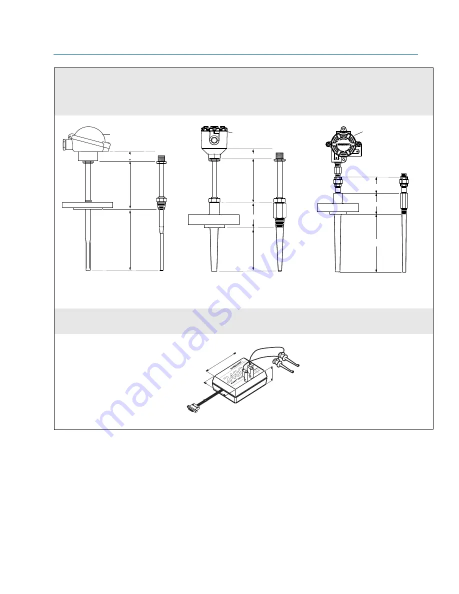
Examples of 248 Transmitter and sensor assemblies with thermowells
Tubular thermowell and
DIN plate style sensor
Barstock thermowell and
DIN plate style sensor
Barstock thermowell, nipple-union
extension, and
1
/
2
-in. NPT spring loaded
sensor
* 80 (3.2) for Class 900 flanges and larger
N = Extension Length, U= Thermowell Immersion Length, Dimensions are in millimeters (inches)
SEE ORDERING TABLES FOR MORE ASSEMBLY OPTIONS
248C configuration interface
Option 1: HART Interface Box
N
U
25 (1.0)
BUZ Connection Head
N
U
40 (1.6)
60 (2.3)
Connection Head
U
N
60 (2.3)*
Universal Head
On
O
ff
+
Se
e w
arn
in
gs o
n b
ack
lab
el
0.61 m (2 ft.)
Configuration Leads
38 (1.5)
1.83 m (6 ft.) Ribbon Cable
84 (3.3)
114(4.5)


