


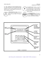


24
MODEL 1054B pH/ORP
SECTION 4.0
CONFIGURATION
4.3.1 Interval Timer Set Up (
Int
).
1.
Enter Set Mode by pressing
ACCESS
key twice.
2.
SCROLL
(
é
) until
Int
appears on the display.
3.
SELECT
to move to the next menu level.
tOn
will
display.
4.
SCROLL
(
é
) to display
on
or
oFF
and
ENTER
it
into memory. If interval configuration is required,
proceed to Step 5, otherwise Step 10.
5.
SCROLL
(
é
) to display desired menu item. If
int
is selected, proceed to Step 6, otherwise Step
10.
6.
SCROLL
(
é
) to display desired interval period
and
SELECT
. The Numeric Display will flash.
7.
SCROLL
(
é
) and
SHIFT
(
ç
) to display the
desired value and
ENTER
it into memory. Display
will return to interval period menu.
8.
Repeat Steps 6 and 7 as needed.
9.
Press the
ENTER
key to return to the main timer
menu.
10.
SELECT
the desired item. The Numeric Display
will flash.
11.
SCROLL
(
é
) and
SHIFT
(
ç
) to display the
desired value and
ENTER
it into memory.
12. Repeat Steps 5, 10, and 11 as required.
13. Press the
ENTER
key to return to the Set Menu.
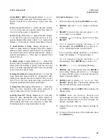
4.3 INTERVAL TIMER.
Display Mnemonic
Int
. This
item is used to set the interval timer's relay logic. The
timer can be used for sensor maintenance, such as
wash cycle or ultrasonic cleaner activation. Refer to
Figure 4-3.
A. Interval Timer Enable/Disable
. Display
Mnemonic
tOn
. Select this item to begin interval cycle
on
or disable interval cycle
oFF
.
B. Interval Period.
Display Mnemonic
int
. Select this
item to set the time period between control cycles.
SEC
for seconds,
uin
for minutes,
hr
for hours, and
dAY
for
days. May be set from a minimum of 10 minutes.
C. Relay Activations Per Cycle.
Display Mnemonic
cnt
. Select this item to enter the number of times the
relay will activate per cycle. May be set from 1 to 60.
D. Relay Activation Duration.
Display Mnemonic
ont
. Select this item to enter the relay activation time
for each
cnt
. May be set from 0 to 299 seconds.
E. Relay Deactivation Duration.
Display Mnemonic
OFt
. Select this item to enter the relay deactivation
time between each
cnt
during the control cycle. Valid
when
cnt
is 2 or greater. May be set from 0 to 299
seconds.
F. Wait Duration.
Display Mnemonic
dur
. Select this
option to enter the electrode recovery time after the
last
cnt
in a cycle. May be set from 0 to 299 seconds.
The duration can be used for electrode recovery after
a wash cycle.
G. Interval Time Remaining
. Display Mnemonic
tiL
.
Select this item to display the time remaining until the
next control cycle. If selected during the control cycle,
the display will show
---
.
NOTE
The Model 1054B pH is placed
on hold
during the control cycle (from first relay
activation through the wait duration).
The analyzer will simulate a fault condi-
tion and briefly show
itr
every eight
seconds. The display will continue to
show the measured value.
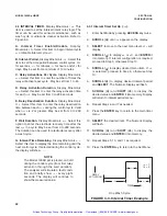
RELAY
ACTIVATION
TIME
int
ont
dur
cnt
= 1
0Ft
= 0
One Wash Cycle
FIGURE 4-3. Interval Timer Example
Artisan Technology Group - Quality Instrumentation ... Guaranteed | (888) 88-SOURCE | www.artisantg.com


