46
Quantum MP User Guide
www.emersonct.com Issue: A4
If a drive is on the end of the network chain then pins 1 and 8 should be
linked together. This will connect an internal 120
termination resistor
between RXTX and RX\TX\. (If the end unit is not a drive or the user
wishes to use their own termination resistor, a 120
termination resistor
should be connected between RXTX and RX\TX\ at the end unit.)
If the host is connected to a single drive then termination resistors
should not be used unless the baud rate is high.
CT Comms cable
The CT Comms cable can be used on a multi-drop network but should
only be used occasionally for diagnostic and set up purposes. The
network must also be made up entirely of Quantum MPs.
If the CT Comms cable is to be used, then pin 6 (TX enable) should be
connected on all drives and pin 4 (+24V) should be linked to at least 1
drive to supply power to the converter in the cable.
Only one CT Comms cable can be used on a network.
4.14 Shield connections
These instructions must be followed to ensure suppression of radio-
frequency emission and good noise immunity in the encoder circuit. It is
recommended that the instructions for the connection of the encoder
cable be followed closely and, to use the grounding bracket and
grounding clamp supplied with the drive, to terminate the shields at the
drive.
4.14.1 Motor cables
Use of a motor cable with an overall shield for the armature and field
circuits may be needed if there is a critical EMC emissions requirement.
Connect the shield of the motor cable to the ground terminal of the motor
frame using a link that is as short as possible and not exceeding 50mm
(2in) long. A full 360° termination of the shield to the terminal housing of
the motor is beneficial.
4.14.2 Encoder cable
To get the best results from shielding use cable with an overall shield
and separate shields on individual twisted pairs. Refer to section
4.17
4.14.3 Control cables
It is recommended that signal cables should be shielded. This is
essential for encoder cables, and strongly recommended for analog
signal cables. For digital signals it is not necessary to use shielded
cables within a panel, but this is recommended for external circuits,
especially for inputs where a momentary signal causes a change of state
(i.e. latching inputs).
4.14.4 Grounding hardware
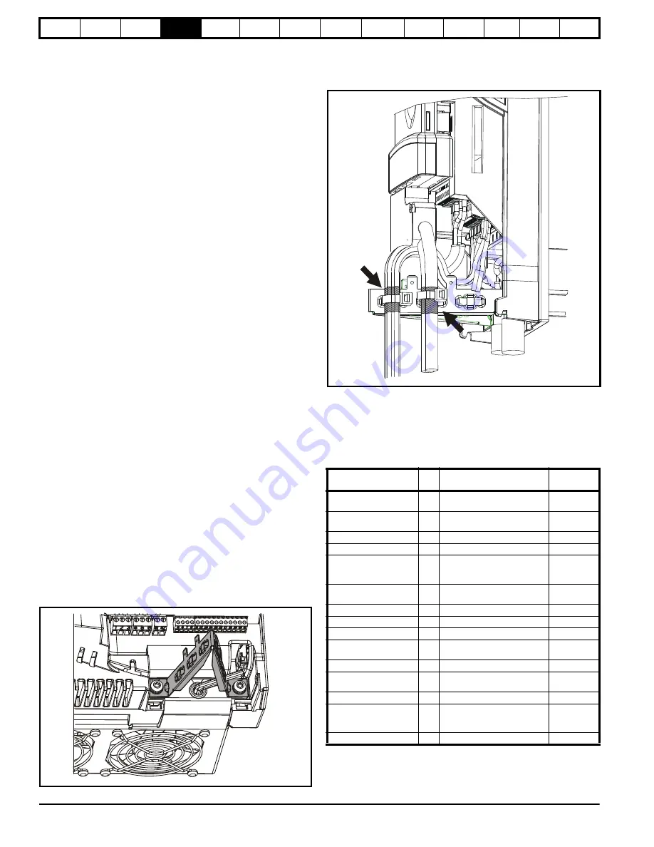
The drive is supplied with a grounding bracket, to facilitate EMC
compliance. This provides a convenient method for direct grounding of
cable shields without the use of "pig-tails". Cable shields can be bared
and clamped to the grounding bracket using metal clips, clamps or cable
ties. Note that the shield must in all cases be continued through the
clamp to the intended drive terminal in accordance with the connection
details for the specific signal.
A faston tab is located on the grounding bracket for the purpose of
connecting the drive 0V to ground should the user wish to do so.
Figure 4-16 Grounding of signal cable shields using the
grounding bracket
4.15 Control connections
Refer to Figure 4-17 to understand the connection of the different power
connections.
4.15.1 General
Table 4-24 The control connections consist of:
Key:
Function
Qty
Control parameters available
Terminal
number
Differential analog input
1
Destination, offset, invert,
scaling
5,6
Single ended analog
input
2
Mode, offset, scaling, invert,
destination
7,8
Analog output
2
Source, mode, scaling,
9,10
Digital input
3
Destination, invert, logic select
27, 28, 29
Digital input / output
3
Input / output mode select,
destination / source, invert,
logic select
Relay
2
Source, invert
51, 52, 53
61, 62, 63
Drive enable
1
Logic select
31
+10V User output
1
4
+24V User output
1
22
0V common
6
1, 3, 11, 21,
23, 30
+24V External input
1
2
120V Line
4
C1, C5, C11,
C13
120V Neutral
1
C15
120V Input
6
Destination, invert
C4, C6, C8,
C10, C12,
C14
120V Output
1
Source, invert
C16
Destination
parameter:
Indicates the parameter which is being controlled by the
terminal / function


