PACMotion™ PSD Installation and User Manual
Section 5
GFK-3168A
September 2020
Mechanical Installation
79
5.12
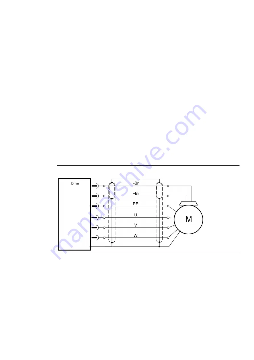
Motor Power Connection (X2)
Together with the motor supply cable and motor winding, the power output of the drive forms an
oscillating circuit. Characteristics such as cable capacity, cable length, motor inductance, and
frequency (
# 37) determine the maximum voltage in the system.
The PSD drive is able to protect the connected motor from overloading, if the parameters are set
correctly and the thermal protection sensor is connected and supervised. With Emerson motors the
valid data are automatically set by the internal motor database. Refer to parameter MOTOR.RTYPE
for supported thermal sensors.
Note: the dynamic voltage rise can lead to a reduction in the motor operating life and, on
unsuitable motors, to flashovers in the motor winding.
•
Only install motors with insulation class F (acc. to IEC60085) or above.
•
Only install cables that meet the requirements (
Note: With long motor cables leakage currents endanger the output stage of the drive. For cable
lengths from 25 m to 50 m, a motor choke (3YL) must be wired into the motor cable (near the
drive). Refer to your regional Accessories Manual for Emerson chokes.
Figure 40: Motor power Connection


