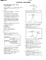

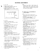


ELECTRICAL ADJUSTMENTS
4. Confirm red and blue c o l o r s
5. Adjust the slant of Ihe deflection yoke while
watching the screen. then tighten the fixing screw.
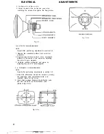
MAGNET
SCRE
W
6
POLE MAGNETS
4 POLE MAGNETS
PURITY MAGNETS
Fig.
3-1
3-3: STATIC CONVERGENCE
NOTE
Adjust after performing adjustmenls in section 3-2.
1. Receive the crosshatch pattern from color bar
generator.
2. Combine red and blue of ‘the 3 color crosshatch
pattern on the center of the screen by adjusting
the pair of 4 pole magnets.
3. Combine red/blue (magenta) and green by
adjusting the pair of 6 pole magnets.
3-4: DYNAMIC CONVERGENCE
NOTE
Adjust after performing adjustments in section 3-3.
1. Adjust the differences around the screen by moving
the deflection yoke upward/downward and
right/left. (Refer to Fig. 3-2-a)
2. Insert three wedges between the deflection yoke
and CRT funnel to fix the deflection yoke.
(Refer to Fig. 3-2-b)
Fig. 3-2-e
WEDGE WEDGE
WEDGE
WEDGE POSITION
Fig. 3-2-b
Содержание Orion TC1972D
Страница 6: ......
Страница 7: ......
Страница 8: ......
Страница 9: ......
Страница 10: ......
Страница 11: ......
Страница 12: ......
Страница 13: ......
Страница 14: ......
Страница 15: ......
Страница 16: ......
Страница 17: ......
Страница 18: ......
Страница 19: ......
Страница 20: ......
Страница 21: ......
Страница 22: ......
Страница 23: ......
Страница 24: ......
Страница 25: ......