Instruction Manual
748467-AJanuary 2002
http://www.processanalytic.com
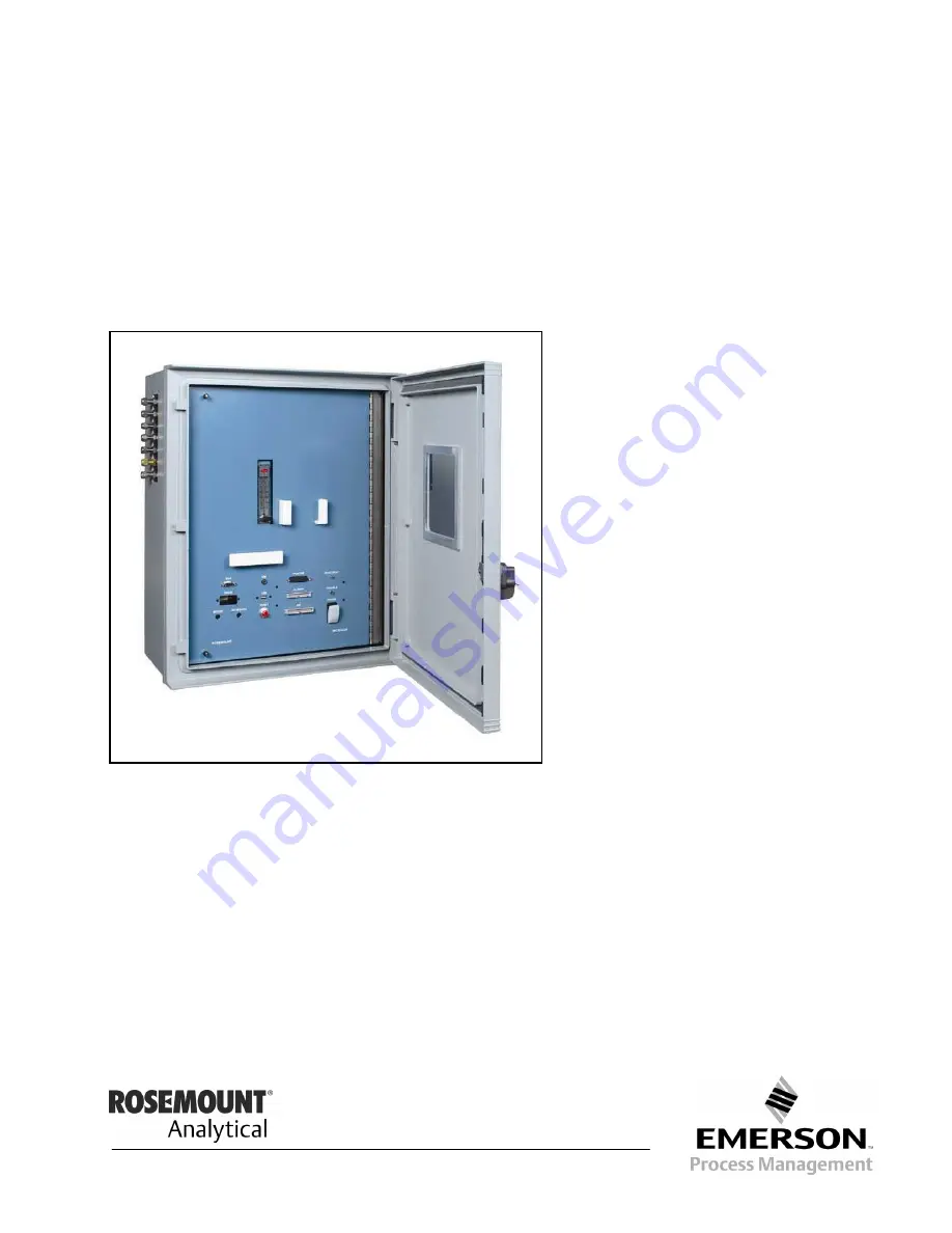
Model MicroCEM
Continuous Emissions Monitor
Страница 1: ...Instruction Manual 748467 A January 2002 http www processanalytic com Model MicroCEM Continuous Emissions Monitor ...
Страница 2: ...our Rosemount Analytical repre sentative for clarification Follow all warnings cautions and instructions marked on and supplied with the product Inform and educate your personnel in the proper installation operation and maintenance of the product Install your equipment as specified in the Installation Instructions of the appropriate Instruction Manual and per applicable local and national codes Co...
Страница 3: ...ersive Infrared NDIR 1 2 b Paramagnetic Oxygen Method 1 6 c Electrochemical Oxygen Method 1 7 1 5 Central Processing Unit 1 9 a Embedded Enhanced Bios 1 9 b Specifications 1 9 1 6 Analog Digital I O Board 1 10 a Automatic Calibration 1 10 b Analog Inputs 1 10 c Programmable Input Ranges 1 11 d Enhanced Trigger and Sampling Control Signals 1 11 e Analog Outputs 1 11 f FIFO and 16 Bit Bus Interface ...
Страница 4: ...oCEM Alarms 3 4 e MicroCEM Login 3 6 f MicroCEM Login Current User Indication 3 6 3 3 MicroCEM Settings 3 7 a Range 3 7 b Auto Calibration 3 8 c Auto Calibration Time and Frequency 3 8 d Manual Calibration 3 9 e Limits 3 10 f Calibration Gas 3 10 g Maintenance Mode 3 11 3 4 MicroCEM Factory Settings 3 12 a PID Control Loop Factory Settings 3 15 3 5 MicroCEM Administration 3 17 a User Settings 3 17...
Страница 5: ...Development Management 4 2 5 0 MAINTENANCE AND SERVICE 5 1 5 1 Overview 5 1 5 2 Converter 5 3 5 3 Ozone Generator 5 4 5 4 Personality Modules 5 4 5 5 Chemiluminescense Detector Assembly 5 5 a Reaction Chamber 5 5 b Photodiode 5 5 6 0 TROUBLESHOOTING 6 1 6 1 Troubleshooting Leaks 6 1 6 2 Pocket PC Connection Failure 6 1 6 3 Trouble LED 6 1 7 0 REPLACEMENT PARTS 7 1 8 0 RETURN OF MATERIAL 8 1 8 1 Re...
Страница 6: ...tions 2 6 Figure 2 6 MicroCEM Wiring Diagram 2 7 Figure 2 7 Leak Test Flow Method 2 14 Figure 2 8 Leak Test Manometer Method 2 15 Figure 3 1 Pocket PC 3 1 Figure 3 2 MicroCEM Front Panel 3 2 Figure 3 3 MicroCEM Pocket PC Display Main Display Shown 3 3 Figure 3 4 MicroCEM Menu 3 4 Figure 3 5 Pocket PC Alarms Screen 3 4 Figure 3 6 MicroCEM Login 3 6 Figure 3 7 Current User Indication 3 6 Figure 3 8 ...
Страница 7: ...igital Output Terminal Assignments 2 12 Table 2 5 RS 232 Interface Terminal Assignments 2 13 Table 2 6 RS 485 Terminal Assignments 2 13 Table 2 7 LAN Interface Terminal Assignments 2 13 Table 2 8 Phone Line Modem Terminal Assignments 2 13 Table 2 9 Antenna Peltier Power Connection Terminal Assignments 2 14 Table 3 1 Status Values 3 3 Table 3 2 Alarm Summary 3 5 Table 3 3 Factory Settings Calibrati...
Страница 8: ...Instruction Manual 748467 A January 2002 vi Contents Rosemount Analytical Inc A Division of Emerson Process Management Model MicroCEM ...
Страница 9: ... following definitions apply to DANGERS WARNINGS CAUTIONS and NOTES found throughout this publication DANGER Highlights the presence of a hazard which will cause severe personal injury death or substantial property damage if the warning is ignored WARNING Highlights an operation or maintenance procedure practice condition statement etc If not strictly observed could result in injury death or long ...
Страница 10: ...ms may be impaired AUTHORIZED PERSONNEL To avoid explosion loss of life personal injury and damage to this equipment and on site property do not operate or service this instrument before reading and understanding this instruction manual and receiving appropriate training Save these instructions DANGER ELECTRICAL SHOCK HAZARD Do not open while energized Installation requires access to live parts wh...
Страница 11: ...on or in this device must be certified to meet the hazardous area classification that the device was certified to prior to any such component addition substitution or replacement In addition the installation of such device or devices must meet the requirements specified and defined by the hazardous area classification of the unmodified device Any modifications to the device not meeting these requi...
Страница 12: ...ual 748467 A January 2002 P 4 Preface Rosemount Analytical Inc A Division of Emerson Process Management Model MicroCEM CAUTION HEAVY WEIGHT Use two persons or a suitable lifting device to move or carry the instrument ...
Страница 13: ...en located in areas where extreme temperatures are prevalent 3 The valve protection cap should be left on each cylinder until it has been secured against a wall or bench or placed in a cylinder stand and is ready to be used 4 Avoid dragging rolling or sliding cylinders even for a short distance they should be moved by using a suitable hand truck 5 Never tamper with safety devices in valves or cyli...
Страница 14: ... instruction materials are available Contact Customer Service Center or the lo cal representative to order See Section 8 748467 Instruction Manual this document 748468 Instruction Manual MicroCEM Sample Handling System COMPLIANCES This product may carry approvals from several certifying agencies The certification marks appear on the product name rating plate CSA Pending ...
Страница 15: ...croCEM NOx Analyzer Module uses the chemiluminescense method of detection This technology is based on NO s reaction with ozone O3 to produce NO2 and oxygen O2 Some of the NO2 molecules produced are in an electroni cally excited state NO2 where the re fers to the excitation These revert to the ground state with emission of photons essentially red light The reactions in volved are NO2 O3 NO2 O2 NO2 ...
Страница 16: ...O2 and Chemiluminescense a Non Dispersive Infrared NDIR The non dispersive infrared method is based on the principle of absorption of in frared radiation by the sample gas being measured The gas specific wavelengths of the absorption bands characterize the type of gas while the strength of the ab sorption gives a measure of the concen tration of the gas component being measured An optical bench is...
Страница 17: ... the absorption of the gas at the corre sponding wavelengths By comparing the measurement and reference wavelength an alternating voltage signal is produced This signal results from the cooling and heating of the pyroelectric detector mate rial Figure 1 1 Absorption Bands of Sample Gas and Transmittance of Interference Filters Transmittance 0 18 36 54 72 90 Transmittance 0 15 30 54 60 75 90 CO2 CO...
Страница 18: ... which is transparent for infrared ra diation The window is usually Calcium Fluoride CaF2 When the infrared radiation passes through the reference side of the analysis cell into the detector no pre absorption occurs Thus the gas inside the absorp tion chamber is heated expands and some of it passes through the flow chan nel into the compensation chamber When the infrared radiation passes through t...
Страница 19: ...er depending on the application and need for reduction of influences Then the infrared radiation enters the analysis cells from which it is focused by filter cells onto the corresponding detector The preamplifier detector output signal is then converted into the analytical results expressed di rectly in the appropriate physical concen tration units such as percent volume ppm mg Nm3 etc This is sho...
Страница 20: ...en molecules enter the cell their paramagnetism will cause them to be drawn towards the region of greatest magnetic field strength The oxygen molecules thus exert different forces on the two suspended nitrogen filled quartz spheres producing a torque which causes the mirror to rotate away from its equilibrium position The rotated mirror deflects the incident light onto the photodetector creating a...
Страница 21: ...the Teflon membrane The electric current between the elec trodes is proportional to the O2 concentra tion in the sample gas being measured The resultant signal is measured as a voltage across the resistor and thermistor the latter of which is used for temperature compensation A change in the output voltage mV represents oxygen concen tration NOTE The electrochemical O2 cell requires a minimum inte...
Страница 22: ...nt Analytical Inc A Division of Emerson Process Management Model MicroCEM Figure 1 6 Electrochemical Oxygen Sensor Lead Wire Anode Lead Wire Cathode Anode Lead O Ring Plastic Disc Plastic Disk Black Red Teflon Membrane Cathode Gold Film Sponge Disc Acid Electrolyte Thermistor Resistor ...
Страница 23: ...e Floppy disk controller the parallel port The CPU is shown in Figure 1 7 a Embedded Enhanced Bios Award 256KB Flash Bios The Bios is immediately activated when you first turn on the system The Bios reads system configuratio information in CMOS RAM and begins the process of checking out the system Figure 1 7 CPU b Specifications Architecture PC AT Compatible Dimensions 5 75 x 8 Processor Intel Til...
Страница 24: ...ion The ADIO board features automatic cali bration of both analog inputs and outputs for enhanced accuracy and reliability The potentiometers which are subject to tam pering and vibration have been elimi nated Instead all A D calibration adjustments are performed using an octal 8 bit DAC The DAC values are stored in an EEPROM and are recalled automati cally on power up The board includes three pre...
Страница 25: ...nchronization of multiple boards and external A D clock ing e Analog Outputs The ADIO board contains 4 12 bit analog outputs with autocalibration capability Up to 5mA of output current per channel can be drawn from all channels simultane ously Both unipolar and bipolar output ranges are supported with jumper con figuration And on power up all outputs are reset to 0V automatically Mode Full scale O...
Страница 26: ...VERTER 12 BIT A D CONVERTERS 1K X8 FIFO 82C54 COUNTER TIMER 10 MHZ OSCILLATOR AUTOCALIBRATION CIRCUIT DC DC BUFFER BUFFER BUFFER BUFFER HIGH CURRENT DRIVE 15V ADDR CTRL 16 BIT DATA 15V 15V PC 104 BUS PROGRAMMABLE GAIN AMP X1 2 4 8 0 31 SE 0 15 DI ANALOG INPUTS ANALOG OUTPUTS 0 3 TIMING AND CONTROL SIGNALS PORT A 24 DIGITAL I O PORT B ACK STROBE PORT CL PORT CH INPUT MUX MASTER CONTROLLER 8255 CIRC...
Страница 27: ...ibration Automatic values stored in EEPROM Analog Outputs Number of outputs 4 D A resolution 12 bits 1 4096 of full scale Output ranges 5 10 0 5 0 10 Output current 5mA max per channel Settling time 6µS max to 0 01 Relative accuracy 1 LSB Nonlinearity 1 LSB monotonic Reset All channels reset to OV Calibration Automatic values stored in EEPROM Digital I O Main I O 24 programmable I O Input current ...
Страница 28: ... Compliant with the PC 104 standard Compatible with AT PC 104 CPU mod ules Functions on board 2 PCMCIA slots Optional remote socket PCMCIA features Supports PCMCIA V 1 0 and V 2 0 Supports PCMCIA types I II and III Supports both I O and Memory Card Supports Hot insertion Operating Systems DOS and Windows and any other RTOS that supports PCMCIA Connectors J1 PCMCIA 2 slots connector J3 PC 104 8 bit...
Страница 29: ...h speed data and fax transmission The PC 104 Modular Modems support both dial up and 2 wire leased line Figure 1 11 depicts the Modem Figure 1 11 Modem a Features V 90 56 kbps data 560PC 104 V 34 33 6 kbps data 336PC 104 14 4 kbps fax Voice playback and record DTMF decode 40o C to 85o C operation 3 775 x 3 550 x 0 568 with modular phone jack 3 775 x 3 550 x 0 435 without modular phone jack 8 bit P...
Страница 30: ...therwise stated All performance timing assumes the controller is in the default i e fastest mode Start up Time Sleep to Write 2 5 msec max Sleep To Read 2 5 msec max Reset to Ready 50 msec typical 400 msec max Data Transfer Rate to from host 16 0 MB sec burst Active to Sleep Delay Programmable Controller Overhead Command to DRQ 1 25 msec Power Requirements All values quoted are typical at ambient ...
Страница 31: ...ercial 0 C to 60 C Operating Industrial 40 C to 85 C Non Operating Commercial 25 C to 85 C Non Operating Industrial 50 C to 100 C Humidity Operating 8 to 95 non condensing Non Operating 8 to 95 non condensing Acoustic Noise 0dB Vibration Operating 15 G peak to peak max Non Operating 15 G peak to peak max Shock Operating 1 000 G max Non Operating 1 000 G max Altitude relative to sea level Operating...
Страница 32: ... screen icons 2 quick keys Record and Scroll Action Notification LED Power Built in Lithium Ion rechargeable battery 8 hours of battery life 1 Worldwide auto voltage AC adapter Input Output IrDA infrared port RS232 serial port USB port Compact Flash Type I card slot AC input jack Stereo earphone jack Sound Audio speaker and microphone Built in voice recorder Digital audio player compatible Other S...
Страница 33: ...dditional security through the use of a 32 character network system ID Standard Support Interoperable with 2 Mbps IEEE 802 11 Direct Sequence Spread Spectrum DSSS and 802 11b 11 and 5 5 Mbps extension OS Support NDIS drivers included for Windows 95 98 ME and NT and 2000 Channels Supports 11 US Canada and 13 ETSI selectable fully independent channels Transmit Power 25mW typical Radio Frequency 2 4 ...
Страница 34: ...te LFM forced air cooling by utilizing a factory installed fan Other features include remote sense power fail logic level inhibit DC power good Main channel current sharing is provided for redundant applications The power supply is approved to the latest international regulatory standards and displays the CE Mark Figure 1 15 500 Watts Power Supply a Features Power Factor Correction PFC Meets EN610...
Страница 35: ... to 50 Celsius Relative Humidity 5 to 99 Inputs Outputs Digital RS 485 Serial Port Multi Drop Network RS 232 Serial Port LAN Ethernet 10 100 BaseT Modem Connectivity Protocols HTML Web Browser Status file transfer Modem Webrowser TCP IP Modbus In Process Foundation Fieldbus In Process Analog Current Outputs 3 Isolated 4 20 mA DC 500 ohms Max Load O2 CO NOX Analog Inputs MW Fuel Flow Digital Output...
Страница 36: ... Celsius Relative Humidity 5 to 99 Instrument Weight 75 lbs Typical Dimensions 24 x 24 x 12 HxWxD Stack Sample Moisture Up to 25 Sample Cooler Thermo Electric dual pass Chiller Permeation Tube 30 C dewpoint Customer instrument air required 5 L M 40 C dewpoint Max Stack Temperature 500 F Higher temperatures available by utilizing elongated spools Stack Pressure 5 to 15 inches H2O Sample Flow Rate 1...
Страница 37: ...AS This unit requires periodic calibration with a known standard gas It also may utilizes a pressurized carrier gas such as helium hydrogen or nitrogen See General Pre cautions for Handling and Storing High Pressure Gas Cylinders page P 5 2 1 OVERVIEW a Limitations Ambient Temperature 30 to 50 Celsius 4 to 122 F Relative Humidity 5 to 99 b Mounting Options Although the MicroCEM is enclosed in an e...
Страница 38: ...17 9 456 9 MOUNTING DIMENSION 1 1 27 9 SAMPLE CALIBRATION GAS 3 GAS 2 GAS 1 OZONE AIR VENT 11 6 295 3 4 3 109 2 4 9 124 5 1 5 38 1 TYP 7 1 180 3 TYP HINGE KEY LOCK 25 2 640 1 20 2 513 1 1 1 27 9 TYP 25 5 647 7 MOUNTING DIMENSION 24 6 624 8 CLEARANCE HOLE FOR 3 8 BOLT 4 PLACES 4 9 124 5 AC POWER INPUT ANALOG INTERFACE DIGITAL INTERFACE RS232 INTERFACE LAN INTERFACE RS485 INTERFACE PHONE LINE ANTENN...
Страница 39: ...fitting outlet and should be LOX clean NOTE All connections specified in the In stallation Drawing in conjunction with the Application Data Sheet should be made b Conditioning All gases must be supplied to the ana lyzer as conditioned gases When the system is used with corrosive gases it must be verified that there are no gas components which may damage the gas path components The gas conditioning...
Страница 40: ...R 904017 2 WAY VALVE MANIFOLD ASSEMBLY GAUGE 638614 FLOWMETER W VALVE CONVERTER 656715 3 WAY VALVE PARAMAGNETIC DETECTOR 90003311 OZONE GENERATOR 659494 NDIR DETECTOR 90003225 IN OUT VENT CAPILLARY 634398 DETECTOR 659754 SAMPLE CAL CAL GAS 3 CAL GAS 2 CAL GAS 1 OZONE AIR EXHAUST Figure 2 2 MicroCEM Gas Connections Figure 2 3 MicroCEM Flow Diagram ...
Страница 41: ...eflon tubing Customer supplied 2 Drain to safe location 1 Customer supplied Electrical connections See Section 2 4 and Figure 2 5 MicroCEM Analyzer Sample Handling System Nitrogen O2 NO High Range O2 NO Mid Range Dry Contact Initiate Auto Calibration 1 1 Sample Flow Stack Sample Inlet FPT Instrument Air Atmospheric Pressure 2 Sample From Analyzer Calibration Line to Analyzer 3 3 Power In 115 VAC 6...
Страница 42: ... specified in the Application Data package All connections are not necessary for every application Cable length for these signals should not ex ceed 3 000 feet 914 meters to avoid exces sive capacitance and corresponding signal distortion All electrical connections are made through the bottom of the MicroCEM enclosure using circular connectors AC POWER INPUT J1 LAN INTERFACE J5 ANALOG INTERFACE J2...
Страница 43: ...IODE DETECTOR SAMPLE PRESSURE SENSOR OZONE PRESSURE SENSOR A9 MOISTURE DETECTOR BAROMETRIC PRESSURE AXX AXX A14 A16 A7 J10 OZONATOR A13 CONVERTER ASSEMBLY J4 J38 J38 J1 J28 J2 J3 A18 P3 PDD A25 A8 NDIR DETECTOR CO A8 NDIR A25 J1 J2 P1 J5 J1 CALIBRATION VALVE ASSEMBLY A12 PMD A24 J3 DS2 GRN J28 J4 J2 J18 J3 P2 TROUBLE HEARTBEAT DS1 RED RS232 DIGITAL ANALOG J3 J2 ANTENNA RS232 LAN RS485 J8 J4 J6 J7 ...
Страница 44: ...Do not cut or damage wire strands Refer to table for proper strip ping dimensions Wire Size Dim A 22O or 22M 125 3 18 20 188 4 77 16 188 4 77 12 188 4 77 Inactive Not recommended for new design replacement only Contact Crimping 1 Insert stripped wire into contact crimp pot Wire must be visible through in spection hole 2 Using correct crimp tool and locator cycle the tool once to be sure the in den...
Страница 45: ... against the contact shoulder 3 Press tool against contact shoulder and with firm and even pressure in sert wired contact and tool tip into center contact cavity A slight click may be heard as metal retaining tines snap into place behind contact shoul der 4 Remove tool and pull back lightly on wire to make sure contact is properly seated Repeat operation with re mainder of contacts to be inserted ...
Страница 46: ...bundle 2 Using plastic or metal extraction tool with proper color code corresponding to contact size place wire in tool 3 Insert tool into contact cavity until tool tip bottoms against the contact shoul der expanding clip retaining tines 4 Hold wire firmly in tool and extract wired contact and tool Repeat op eration for all contacts to be ex tracted 5 Fill any empty wire cavities with wire sealing...
Страница 47: ...able 2 6 Phone Line Modem J7 8 3 24 22 20 Table 2 8 Antenna Peltier Power J8 16 3 14 12 Table 2 9 Table 2 1 Interface Connections SIGNAL NAME DEFINITION PIN L1 A L2 85 264 VAC 47 440 Hz C GND AC Ground B Table 2 2 AC Power Connection Terminal Assignments SIGNAL NAME DEFINITION PIN O2CL 1 O2CL O2 Reading 4 20 mA Output 2 COCL 3 COCL CO Reading 4 20 mA Output 4 NOX 5 NOX NOX Reading 4 20 mA Output 6...
Страница 48: ... 10 CALC 11 CALNC Calibration Valve Control Dry contact 110V 1A Rating 12 TRBLNO 13 TRBLC 14 TRBLNC Trouble Indicator Dry contact 110V 1A Rating 15 O2LR 16 O2LR O2 Low Reading Digital output 0 LR 17 COLR 18 COLR CO Low Reading Digital output 0 LR 19 NOxLR 20 NOxLR NOx Low Reading Digital output 0 LR 21 EXTDIG1 22 EXTDIG1 Digital Input from External process 23 INCAL 24 INCAL Initiate Calibration Sw...
Страница 49: ... Signal Ground 9 Not Used 10 13 Table 2 5 RS 232 Interface Terminal Assignments SIGNAL NAME DEFINITION PIN TxD RxD pin 2 A TxD RxD pin 7 Bi directional Data B GND pin 3 Ground C Table 2 6 RS 485 Terminal Assignments SIGNAL NAME DEFINITION PIN TxD pin 1 1 TxD pin 2 Transmit Data 2 RxD pin 3 3 RxD Pin 6 Receive Data 4 Not Used 5 6 Table 2 7 LAN Interface Terminal Assignments SIGNAL NAME DEFINITION P...
Страница 50: ...lves breaking the integrity of the sample containment system a Flow Indicator Method Supply air or inert gas such as nitrogen at 10 psig 689 hPa to the analyzer through a flow indicator with a range of 0 to 250 cc min Install a shut off valve at the sample gas outlet Set the flow rate to 125 cc min Close the outlet shut off valve and notice that the flow reading drops to zero If the flow reading d...
Страница 51: ...il the analyzer is pressurized to approxi mately 50 hPa The water column will be about 500 mm Close the inlet shut off valve and follow ing a brief period for pressure equilibrium verify that the height of the water column does not drop over a period of about 5 minutes If the water column height drops the system is leaking and must be cor rected before the introduction of any flammable sample gas ...
Страница 52: ...Instruction Manual 748467 A January 2002 2 16 Installation Rosemount Analytical Inc A Division of Emerson Process Management Model MicroCEM ...
Страница 53: ...e installed detector s Analyzer operation can be confirmed on the screen of the pocket PC through the glass window on the door Upon power up the analyzer will perform a self test routine This test will last approximately 60 sec onds 3 2 POCKET PC USER INTERFACE The MicroCEM User Interface runs on a Pocket PC with Windows CE operating system It communicates with the Micro CEM via serial communicati...
Страница 54: ...vision of Emerson Process Management Model MicroCEM Figure 3 2 MicroCEM Front Panel RS232 Connector 5V Connector Mouse Connector VGA Connector Keyboard Connector USB Connector Reset Button Printer Connector Floppy Connector IDE Connector Heartbeat LED Trouble LED Power Switch Flowmeter ...
Страница 55: ...precedence Maintenance mode status takes highest prece dence Figure 3 3 MicroCEM Pocket PC Display Main Display Shown STATUS DESCRIPTION M Indicates that maintenance mode is active C Calibration in process I Invalid Reading Indicates that the reading is invalid due to calibration failure or sensor failure V Valid Reading P Customer Process Off Line Dry contact by customer O MicroCEM System Off Tab...
Страница 56: ... also shown non active acknowledged alarms Up to 100 alarms will be shown To see more than the last 100 alarms the web based MicroCEM interface must be used If one or more alarms are cur rent the most recent of them will be displayed on the main display If more than one alarm is current more will be displayed after the name of the most recent alarm on the main window to in dicate that more than on...
Страница 57: ...x Critical 24V diagnostic input exceeds the specified maximum 24 Low Min Critical 24V diagnostic input is below the specified minimum O2 Emission Limit Warning O2 reading is over the specified Limit CO Emission Limit Warning CO reading is over the specified Limit NOx Emission Limit Warning NOx reading is over the specified Limit Converter Over Temp Critical Converter temperature reading exceeds th...
Страница 58: ... to the User Settings page of the Micro CEM Settings dialog After logging in the first time it is not required again until the user logs out or is logged out automatically because of a period of in activity Refer to the Auto Logout page of the MicroCEM Administration dialog Figure 3 6 MicroCEM Login f MicroCEM Login Current User Indi cation When a user is logged in the Micro CEM main display will ...
Страница 59: ...tially a Range The Range Settings page is used to set the range of the Emissions analog out puts The outputs support dual range mode When the emission is below the Range 1 value the output switches to Range 1 mode and the Range 1 value becomes the full scale value of the out put The range indication digital output will change to the Range 1 state When the emission is above the Range 1 value the ou...
Страница 60: ...ngs If auto calibration is turned to the on position then the user can select time and or frequency of the auto calibration in the Auto Calibration Frequency tab Section 3 3c Figure 3 9 Auto Calibration Settings c Auto Calibration Time and Fre quency The Auto Calibration Time and Fre quency tab allows specifying time and frequency of the auto calibration Time field requires military time format Fi...
Страница 61: ... more of the emission types While the manual calibration is in process a calibration progress dialog will be displayed as shown in Figure 3 26 When the manual calibration is completed the results are displayed in the Manual Calibration Results dialog as shown in Figure 3 12 If the Local Calibration checkbox is checked the Local Calibration valve will be used during the calibration rather than the ...
Страница 62: ...s display It is also indicated in the limit exceeded digital output Figure 3 13 Limit Settings f Calibration Gas The Calibration Gas emissions quanti ties and Gas Bottle allocation may be set on the Calibration Gas page of the MicroCEM Settings This should be set whenever a Calibration Gas container is replaced Place the span gas value of the par ticular gas cylinder in the span column I mid calib...
Страница 63: ... 11 Model MicroCEM g Maintenance Mode Maintenance mode may be selected for any of the emission types on the Main tenance Mode page of the MicroCEM Settings Choosing maintenance mode will in voke an M flag onto the data Cus tomer can perform routine maintenance while in this setting Figure 3 15 Maintenance Mode Settings ...
Страница 64: ...e by MicroCEM technicians to set parameters in the MicroCEM or a qualified customer technician Enter the Factory Settings password at the login dia log to enter the Factory Settings This password will not be provided to the cus tomer The list of settings is shown in Ta ble 3 3 and Table 3 4 The user must purchase a PC 104 to mouse and PC 104 to monitor in order to access the factory settings Consu...
Страница 65: ...es for the emissions conversion slope and offset used on a new system before the first Cali bration is performed These values should be set manually before the first auto calibration is per formed O2SpanDef Default O2 Span Calibration Gas value O2MidSpanDef Default O2 Mid Span Calibration Gas value COSpanDef Default CO Span Calibration Gas value COMidSpanDef Default CO Mid Span Calibration Gas val...
Страница 66: ...ng is made when the sync goes from high to low Reference R or Sample Gas S 24V Low Limit If the 24V measurement is below this level it will cause an alarm 24V High Limit If the 24V measurement is above this level it will cause an alarm ValveOnTime For calibration The amount of time to wait after turning on a valve O2EmissionLimit NOXEmissionLimit COEmissionLimit O2LowRange COLowRange NOXLowRange O...
Страница 67: ...ol loops The temperature control loops include the Zone heater cooler Converter Heater PMT Heater and PMT Photo Diode Cooler Table 3 5 shows the section names in the INI file used for each temperature control loop Control Loop Section Name Zone Heater Cooler PIDSettings ZoneLoop Converter Heater PIDSettings ConverterLoop PMT Heater PIDSettings PMTLoop PMT Photo Diode Cooler PIDSettings PDTLoop Tab...
Страница 68: ... and Derivative gain ResetIntegralError Integral Reset Error Setting used to reset Integral value when error is larger than this value This parameter is used to prevent the integral value from building up while the error is large and then causing overshoot when the setpoint is reached IntegralMaxPercent Maximum percent output power that can be accumulated by the Integral component 0 100 The defaul...
Страница 69: ...M Administration tabbed dialog is displayed The User Set tings page tab is displayed initially a User Settings The user settings page of the Micro CEM Administration dialog allows users to be added deleted or modified Each user has a name password and per mission settings The permission set tings include Settings permission that allows access to the MicroCEM Set tings dialog and Administrative per...
Страница 70: ...le is overwritten when new ones are cre ated Emissions Log 6 Calib Log 6 Alarm Log 6 c Log File Name Format The log file name uses the date that the file was created It is of the format TYYYYMMDD CSV where T is the log file type E Emissions C Calibration and A Alarm YYYY is the Year MM is the month and DD is the day of the month For example the file name E20010329 csv contains emissions data and w...
Страница 71: ...f calibration 0 0 O2 Zero Drift Percent drift of O2 zero calibration 0 0 O2 Measured Mid Span Measured percent O2 for Mid span phase of calibration 10 1 O2 Expected Mid Span Expected percent O2 for Mid span phase of calibration 10 0 O2 Mid Drift Percent drift of O2 mid calibration 0 4 O2 Measured Span Measured percent O2 for Span phase of calibration 20 2 O2 Expected Span Expected percent O2 for S...
Страница 72: ...igh Limit 6 CO Low Limit 7 NOx High Limit 8 NOx Low Limit 9 O2 Emission Limit 10 CO Emission Limit 11 NOx Emission Limit 12 5 Volt Fault 13 6 Volt Fault 14 24V Over Max 15 24 Low Min 16 Converter Over Temp 17 Converter Low Temp 18 Converter On Failed 19 Converter Off Failed 20 Zone Over Temp 21 Zone Low Temp 22 Zone Heater On Failed 23 Zone Heater Off Failed 24 Zone Cooler On Failed 25 Zone Cooler...
Страница 73: ...s may be selected to view the calibration log and the alarm log Figure 3 18 View Data Logs Average Period Time Range Displayed 1 Minute 1 Hour 15 Minutes 1 Day 1 Hour 3 Days 12 Hours 1 Month 24 Hours 3 Months Table 3 10 Average Period Selection Select 1 min 15 min 1 hour or 24 hour averages Select the ending hour to view applicable only to 1 minute averages If Most Recent is selected the month day...
Страница 74: ...ation menu but these pages are intended for remote desktop use As an enhancement these items could be hidden if the pages are browsed from a Windows CE version of Internet Explorer Figure 3 19 View Data Logs Table Alarms and Calibration data may also be viewed The Emission Data Logs data is shown here A Date is shown for 1 min or 15 minute averages A date range is shown for 1 hour or greater avera...
Страница 75: ...t connection PPP or Dialup Connection RAS The MicroCEM has Window CE Web Server in stalled and provides a Web based interface to select and download the Data Log files The downloaded Data Log files will be in a CSV comma delineated ASCII format The log files may also be viewed as a web page in a tabular format a Real Time Page The Real Time page provides a real time display of the emission values ...
Страница 76: ...he Date and Average Period and pressing the Display button If de sired a bookmark or shortcut may be made to the page displaying the table In the future the same table can be displayed by selecting this bookmark If Most Recent Data was selected the book marked page will always display Most Recent Data If a specific date was specified the book marked page will always display the same date Figure 3 ...
Страница 77: ...Instruction Manual 748467 A January 2002 Rosemount Analytical Inc A Division of Emerson Process Management Operation 3 25 Model MicroCEM Figure 3 23 Calibration Table ...
Страница 78: ...e selection is made press the Download button to start the HTTP download The Micro CEM will create a temporary file that contains the selected data Due to memory limitations there is a limit to the number of files that can be downloaded simultaneously If this limit is ex ceeded a message will be displayed that reads The simultaneous download limit has been reached please try again later Figure 3 2...
Страница 79: ...ally refreshes the spreadsheet with data from the web site To do this first make sure the MicroCEM web site is available The workstation needs access to the MicroCEM web site via RAS Dialup LAN or the Internet Then in Excel select Data menu Get External Data New Web Query The dialog shown in Figure 3 25 will appear Type in the ad dress for a MicroCEM web page that contains a table with the desired...
Страница 80: ...dialog is displayed whenever calibration is in process It dis plays the current emission values and the status of the calibration The calibration may be canceled before it completes by pressing the Cancel button Note The title of this dialog will read either Auto Calibration or Manual Calibration to indicate how the cali bration process was initiated Figure 3 26 Auto Calibration ...
Страница 81: ...normally run locally since there is no input device or display connected to the MicroCEM processor 4 3 MicroCEM WEB SERVER SOFTWARE Web Browser Internet Explorer 4 0 or Net scape 4 0 The Web Server Software provides the web based interface described in this document It is implemented as a VB Script or Java Script The script will obtain much of the needed in formation directly from the Data Log fil...
Страница 82: ...ical Inc A Division of Emerson Process Management Model MicroCEM 4 4 SOFTWARE DEVELOPMENT MANAGEMENT Microsoft Visual SourceSafe is used for ver sion control of all of the MicroCEM software Compuware s Track Record is used for change request management and defect tracking ...
Страница 83: ...factory approved components for repair 5 1 OVERVIEW The MicroCEM Analyzer Module requires very little maintenance during normal operation Occasionally the detector s reaction chamber and sapphire window may require cleaning refer to Section 5 5 White crystal deposits on the windows of the reaction chamber and plugging of capillaries and vent are usually due to sample contami nates such as ammonia ...
Страница 84: ... Management Model MicroCEM Figure 5 1 MicroCEM Component Location Ozone Generator NDIR Detector Converter Figure 5 2 Valve Manifold Assembly Paramagnetic Detector 3 Way Valve Transistor Personality Modules Figure 5 3 Power Relay Fan Power Supply Assembly Thermoelectric Cooler Regulator Chemiluminescense Detector Figure 5 4 ...
Страница 85: ...wo pneumatic tubes and two electri cal connections Unlace the heater blanket and remove the converter Reassemble in re verse order ensuring that the converter is ori ented with the glass cloth at the bottom and the sensor is oriented correctly inside the heater jacket Figure 5 2 Converter Assembly ASSEMBLED SIDE VIEW Converter Tube 655227 Wrap with aluminum foil Glass Cloth Sensor Heater Jacket 65...
Страница 86: ...e different personality modules Depending on your unit you may have three four or five modules installed These person ality modules are installed on a custom back plane See Figure 5 3 To remove any on the personality modules Remove cables form module to be removed there are two screws at the bottom of each module You will have to loosen each screw before you can remove the personality mod ule Tag ...
Страница 87: ...Chamber O ring and window into position and the tubing into the slot in the housing Hold the Reaction Chamber in place while rotating the housing upright Replace the hold down screws NOTE Component Positioning The proce dure described above is for the pur pose of maintaining the relative positions of windows and O ring to the Reaction Chamber during installation Replace the top cap and screws Reve...
Страница 88: ...istors etc with the thicker shim washer on the opposite side of the socket from the thermistor Replace the lower section of the housing then the bottom cover insulator and bracket with the shoulder washers and screws Re tighten the screws in the Reaction Chamber upper section Replace the top cap and its screws To reinstall in the Analyzer Module re verse the procedure for removal as indi cated abo...
Страница 89: ...ainer Gasket Detector Header M3X0 5 x 25mm Screw 2 3mm Spring Washer 2 O Ring 876478 Photodiode Assembly see detail below see detail below M3X0 5 x 20mm Screw 2 3mm Spring Washer 2 Detector Cover M3X0 5 x 16mm Screw 2 3mm Spring Washer 2 Photodiode Cable Lower Cover Insulator between Lower Cover and Mounting Bracket Nylon Shoulder Washers 3 Photodiode Case Ground M3X0 5 x 16mm Screw 3 Thermistor 6...
Страница 90: ...Instruction Manual 748467 A January 2002 5 8 Maintenance and Service Rosemount Analytical Inc A Division of Emerson Process Management Model MicroCEM ...
Страница 91: ...separately For analyzers with parallel gas paths the leak check must be performed for each gas path separately 6 2 POCKET PC CONNECTION FAILURE In the event the connection between the Pocket PC and the MicroCEM fails a connection failure dialog will be displayed It will display the fol lowing message Connection with uCEM lost retrying A Cancel button will be displayed The Micro CEM software will c...
Страница 92: ...Instruction Manual 748467 A January 2002 6 2 Troubleshooting Rosemount Analytical Inc A Division of Emerson Process Management Model MicroCEM ...
Страница 93: ...Module Assembly 1020869 100 Thermoelectric Cooler Assembly 1020973 100 Thermistor 1020987 100 Heater Assembly 42706504 Desiccant Bulbs 42711801 Electrical Cable 634398 Capillary Vent 638614 Pressure Gauge 655216 Thermistor Assembly 655250 Converter Assembly 655289 Restrictor Bulkhead 657716 Power Supply Ozonator 657719 Ozone Generator 658157 Restrictor Brass 659754 Photodiode Detector 90003311 Par...
Страница 94: ...Instruction Manual 748467 A January 2002 7 2 Replacement Parts Rosemount Analytical Inc A Division of Emerson Process Management Model MicroCEM ...
Страница 95: ... 5 Enclose a cover letter and purchase order and ship the defective equipment accord ing to instructions provided in the Rose mount Return Authorization prepaid to Rosemount Analytical Inc Process Analytic Division Customer Service Center 1 800 433 6076 If warranty service is expected the defective unit will be carefully inspected and tested at the factory If the failure was due to the condi tions...
Страница 96: ...Instruction Manual 748467 A January 2002 8 2 Return of Material Rosemount Analytical Inc A Division of Emerson Process Management Model MicroCEM ...
Страница 97: ...tly or indirectly arising from the use of the equipment or goods from breach of any warranty or from any other cause All other warranties expressed or implied are hereby excluded IN CONSIDERATION OF THE HEREIN STATED PURCHASE PRICE OF THE GOODS SELLER GRANTS ONLY THE ABOVE STATED EXPRESS WARRANTY NO OTHER WAR RANTIES ARE GRANTED INCLUDING BUT NOT LIMITED TO EXPRESS AND IMPLIED WARRANTIES OR MERCHA...
Страница 98: ...ent Singapore 128461 Republic of Singapore Phone 65 777 8211 Fax 65 777 0947 http www processanalytic com EUROPEAN TECHNOLOGY CENTER Fisher Rosemount GmbH Co Industriestrasse 1 63594 Hasselroth Germany Phone 49 6055 884 0 Fax 49 6055 884209 EUROPE MIDDLE EAST AND AFRICA Fisher Rosemount Ltd Heath Place Bognor Regis West Sussex PO22 9SH England Phone 44 1243 863121 Fax 44 1243 845354 LATIN AMERICA ...