


Maintenance Bypass Cabinet
28
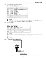
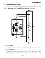
7. Connect the system input cables between the Maintenance Bypass Cabinet 'UPS Input' Busbars
(A-B-C N terminals) and UPS input busbars (A-B-C N terminals) and tighten the connections to
44 lb-in. (5 N-m) (M6 bolt).
8. Connect the system outnput cables between the Maintenance Bypass Cabinet 'UPS Output'
Busbars (A-B-C N terminals) and UPS output busbars (A-B-C N terminals) and tighten the
connections to 44 lb-in. (5 N-m) (M6 bolt).
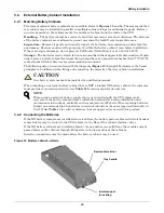
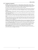
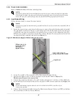
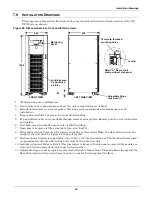
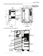
9. Connect supplied control wire to X3 on the Parallel (M3) board (see
Figure 20
).
Figure 20 Maintenance bypass control wire location
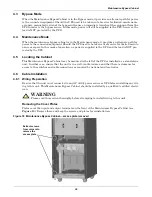
!
WARNING
The control wire must be installed to ensure proper operation of the system and fully protect
the load when switching between bypass cabinet and UPS.
NOTE
For startup procedure, see the UPS operations and maintenance manual, SL-25210.
485-
P2
X2
2
485+
DBS
X3
P1
X2
1
:XT
M
A IN
T
Terminal Block Location
Содержание Liebert NX
Страница 1: ...AC Power For Business Critical Continuity Liebert NX UPS Installation Manual 10 30kVA 208V 60Hz ...
Страница 2: ......
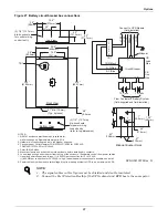
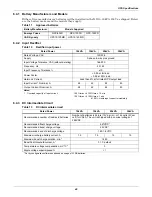
Страница 51: ...Installation Drawings 45 Figure 32 Location of internal batteries Battery 417mm 687mm 186mm ...
Страница 77: ...Specifications and Technical Data 71 NOTES ...
Страница 78: ...Specifications and Technical Data 72 ...
Страница 79: ......