Emerson Fisher SS-263 Скачать руководство пользователя страница 9

Instruction Manual

D103542X012

SS-263 Volume Booster

September 2019

9

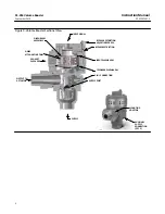
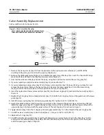
14.  Apply lubricant (key 18) to the O-ring (4H) and the outside diameter of the spring seat (4F).

15.  Install the upper spring (key 6) and the spring case assembly (key 3) on the upper diaphragm (key 4C).

CAUTION

To avoid damage to the diaphragms, do not overtighten the screws.

16.  Replace the six cap screws (key 10) and tighten them in a crisscross manner using multiple patterns working up to a

final torque of 15.8 N•m (140 lbf•in).

Parts Ordering

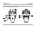
Whenever corresponding with your 

Emerson sales office

 about this equipment, mention the serial number of the valve

assembly. This serial number can be found on the actuator nameplate. It may also be helpful to mention the date and
other information on the volume booster nameplate as shown in figure 2.

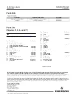
When ordering replacement parts, state the complete eleven-digit part number of each part required as found in the
following parts list.

  WARNING

Use only genuine Fisher replacement parts. Components that are not supplied by Emerson Automation Solutions should
not, under any circumstances, be used in any Fisher instrument, because they may void your warranty, might adversely
affect the performance of the valve, and could cause personal injury and property damage.

Содержание Fisher SS-263

Страница 1: ...is important to carefully read understand and follow all the contents of this manual including all safety cautions and warnings If you have any questions about these instructions contact your Emerson sales office before proceeding Description The SS 263 volume booster is used exclusively in Fisher Optimized Digital Valve ODV packages The booster amplifies the output signal from the FIELDVUE digita...

Страница 2: ... the PED Directive 2014 68 EU It was designed and manufactured in accordance with Sound Engineering Practice SEP and cannot bear the CE marking related to PED compliance However the product may bear the CE marking to indicate compliance with other applicable European Community Directives Approximate Weight Aluminum 3 6 kg 8 lbs Stainless Steel 10 8 kg 24 lbs NOTE Specialized instrument terms are d...

Страница 3: ...ry due to bursting of pressure containing parts or explosion of accumulated gas Check with your process or safety engineer for any additional measures that must be taken to protect against process media Note Do not use separate pressure supplies for the volume booster and associated positioner The volume booster may not exhaust immediately upon loss of a separate pressure supply However if the sys...

Страница 4: ...ter Sectional View BYPASS RESTRICTION ADJUSTING SCREW SUPPLY PORT OUTPUT TO ACTUATOR BYPASS RESTRICTION INPUT SIGNAL SUPPLY DIAPHRAGM ASSEMBLY EXHAUST PASSAGES INPUT DIAPHRAGM FEEDBACK DIAPHRAGM NOISE ATTENUATING TRIM 3 IN 1 CONNECTION X0206 MOUNTING ADAPTOR AUXILIARY SUPPLY CONNECTION QTY 2 ...

Страница 5: ...pe elbow key 34 3 Install O ring key 30 into the groove in the mounting adaptor key 29 4 Using studs key 31 lock washers key 33 and hex nuts key 32 mount the SS 263 onto the actuator Tighten hex nuts key 32 to 50 ft lbs Pressure Connections The input signal connection is 1 4 NPT the supply connection is 1 NPT and the output connection is 1 NPT or 1 1 4 NPT depending on application Ensure that the ...

Страница 6: ...iple of Operation Refer to figure 3 Because of the restriction large input signal changes register on the booster input diaphragm sooner than in the actuator A large sudden change in the input signal causes a pressure differential to exist between the input signal and the feedback diaphragm of the booster When this occurs the diaphragms move to open either the supply port or the exhaust port which...

Страница 7: ...gm assembly key 4 4 Replace the two O rings key 22 5 Carefully install the diaphragm assembly key 4 into the diaphragm spacer assembly key 2 by folding the upper diaphragm key 4C inward Rotate the diaphragm assembly key 4 until the oversized hole in each diaphragm aligns with the flow passage in the diaphragm spacer assembly key 2 6 Install the diaphragm assembly key 4 and the diaphragm spacer ass...

Страница 8: ...ring key 5J Remove the lower valve and stem key 5B from the seat ring key 5A 6 Insert the replacement lower valve and stem key 5B into the seat ring key 5A and install the hex nut key 5E on the stem 7 Replace the O ring key 5H and apply lubricant key 18 to both the O ring key 5H and the guide bore of the lower guide key 5F 8 Install the lower spring key 5J and the lower guide key 5F Tighten to 61 ...

Страница 9: ...your Emerson sales office about this equipment mention the serial number of the valve assembly This serial number can be found on the actuator nameplate It may also be helpful to mention the date and other information on the volume booster nameplate as shown in figure 2 When ordering replacement parts state the complete eleven digit part number of each part required as found in the following parts...

Страница 10: ...Instruction Manual D103542X012 SS 263 Volume Booster September 2019 10 Figure 6 Volume Booster Assembly Drawing APPLY LUB SEALANT GE49000 A ...

Страница 11: ...Instruction Manual D103542X012 SS 263 Volume Booster September 2019 11 Figure 7 Volume Booster Assembly with Mounting Adaptor GE56173 A ...

Страница 12: ...shing 29 Mounting Adaptor 30 O ring see parts kit 31 Stud 2 req d 32 Hex Nut 2 req d 33 Lock Washer 2 req d 34 1 1 4 NPT Pipe Elbow Recommended spare parts Emerson Automation Solutions Marshalltown Iowa 50158 USA Sorocaba 18087 Brazil Cernay 68700 France Dubai United Arab Emirates Singapore 128461 Singapore www Fisher com The contents of this publication are presented for informational purposes on...

Отзывы: