Instruction Manual
D103292X012
C1 Controllers and Transmitters
March 2017
19
change in the opposite direction than expected. For example, while moving the calibration adjuster to increase span, the output
pressure may decrease. This should be disregarded since even though the output pressure decreases, the span is increasing.
Proper controller response depends on nozzle-to-flapper alignment.
When performing span adjustments, carefully loosen both calibration adjuster screws while holding the calibration adjuster in
place. Then move the calibration adjuster slightly in the required direction by hand or using a screwdriver. Verify proper
nozzle-to-flapper alignment and hold the calibration adjuster in place while tightening both adjustment screws.
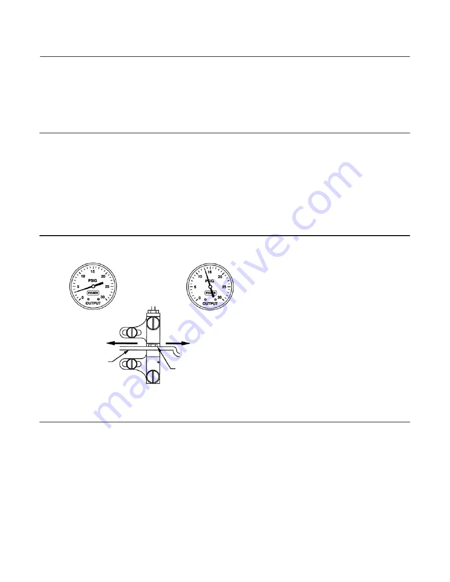
11. If the output pressure is not between 0.6 and 0.7 bar (8 and 10 psig), adjust the controller span by loosening the
12. Repeat steps 6 through 11 until no further adjustment is necessary.
13. For C1P and C1B controllers with anti-reset windup remove the two machine screws, anti-reset windup cover, and
14. Proceed to the Startup procedures for proportional-plus-reset controllers.
Figure 9. Direct-Acting Controller Span Adjustment —Proportional-Plus-Reset Controllers
IF OUTPUT IS:
BELOW
8 TO 10 PSIG
(0.6 TO 0.7 BAR)
ABOVE
8 TO 10 PSIG
(0.6 TO 0.7 BAR)
MOVE ADJUSTER
LEFT
MOVE ADJUSTER
RIGHT
FLAPPER
NOZZLE
NOTE:
3 TO 15 PSIG (0.2 TO 1.0 BAR) OUTPUT SHOWN.
FOR 6 TO 30 PSIG (0.4 TO 2.0 BAR) OUTPUT, ADJUST
VALUES AS APPROPRIATE.
A6154
Calibration: Anti-Reset Windup
Controllers with anti-reset windup have a differential relief valve assembly (figure 23). This relief valve is set at the
factory to relieve at a 0.3 bar (5 psi) pressure difference between the reset bellows pressure and the proportional
bellows pressure. The valve can be adjusted to relieve from 0.14 to 0.4 bar (2 to 7 psig).
The relief valve can relieve on either rising controller output pressure or falling controller output pressure. If the arrow
on the relief valve points toward the bottom of the controller case as shown in figure 23, the valve will relieve on falling
output pressure. If the arrow points in the opposite direction, the valve will relieve on rising output pressure. The valve
can be removed and reinstalled with the arrow pointing in the opposite direction to change the relief action.


