Instruction Manual
D200149X012
3610J and 3620J Positioners
September 2017
34
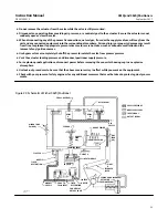
Figure 21. Schematic of Fisher 3611JP Positioner
38A8902‐B
B1846‐1
MINOR LOOP
GAIN ADJ
ZERO ADJ
RANGE SPRING
COARSE
SPAN
ADJ
CROSS‐OVER
ADJ
RELAY BEAM
RELAY
B
RELAY
A
SUPPLY PRESSURE
NOZZLE PRESSURE
INPUT SIGNAL
OUTPUT SIGNAL
OUTPUT SIGNAL
AIR SUPPLY
FINE
SPAN
ADJ
PIVOT B
INPUT MODULE
PIVOT A
FLAPPER
NOZZLE
FIXED
RESTRICTION
AIR SUPPLY
CAVITY A
CAVITY B
INPUT SIGNAL
PRESSURE
PISTON
ACTUATOR
SUMMING BEAM
COUNTER SPRING
FEEDBACK
LEVER
Maintenance
Positioner parts are subject to normal wear and must be inspected and replaced as necessary. The frequency of
inspection and replacement depends upon the severity of service conditions. The following procedure describes
disassembly and reassembly of the positioner. When inspection or repairs are required, disassemble only those parts
necessary to accomplish the task. When reassembly is complete, make adjustments as described in the Calibration
section.
WARNING
Avoid personal injury or property damage from sudden release of process pressure. Before performing any maintenance
operations:
D
Always wear protective clothing, gloves, and eyewear when performing any maintenance operations to avoid personal
injury.


