Service Instructions
074985 Rev. B
October 2014
22
Appendix
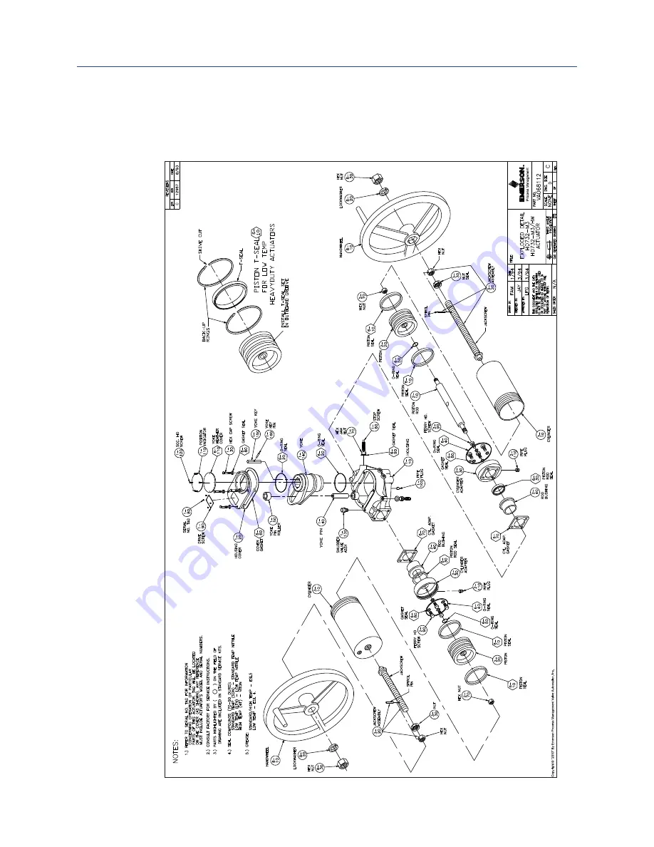
A.3
Part No. VA063356, HD732-M3/HD732-M3/HW
Actuator, Exploded Detail Drawing
Страница 1: ...Service Instructions 074985 Rev B October 2014 Bettis Disassembly and Reassembly ForModelsHD732 SDouble ActingSeriesHydraulicActuators ...
Страница 2: ......
Страница 3: ...rials Section 4 General Section 5 General Disassembly Section 6 Pressure Cylinder Disassembly Section 7 Housing Group Disassembly Section 8 General Reassembly Section 9 Center Housing Group Reassembly Section 10 Pressure Cylinder Reassembly Section 11 Actuator Testing Section 12 Return to Service Section 13 M3 Jackscrew Disassembly Section 14 M3 Jackscrew Reassembly Section 15 Document Revision Ap...
Страница 4: ...el working on Bettis actuators this procedure should be reviewed and implemented for safe disassembly and reassembly Close attention should be noted to the WARNINGS CAUTIONS and NOTES contained in this procedure 3 DEFINITIONS WARNING If not observed user incurs a high risk of severe damage to actuator and or fatal injury to personnel CAUTION If not observed user may incur damage to actuator and or...
Страница 5: ...maximum recommended service interval for this actuator series is five years Storage time is counted as part of the service interval 6 This procedure is applicable with the understanding that all electrical power and hydraulic pressure has been removed from the actuator Also it is understood that the actuator has been removed from the valve as well as all piping and accessories that are mounted on ...
Страница 6: ...port Items Service Seal Kit commercial leak testing solution and non hardening thread sealant 2 2 Tools All tools are American Standard inch Two each medium standard screwdriver small standard screwdriver with corners rounded putty knife rubber or leather mallet and a torque wrench up to 2 000 inch pounds For recommended tool list refer to Page 17 ...
Страница 7: ...umber 036278 2 Exploded Detail Drawing 063356 for HD732 actuators 3 Exploded Detail Drawing 068112 for HD732 M3 and HD732 M3HW actuators The drawings called out in the above Steps 1 through 3 are for pneumatic operated actuators and will not call out the bleed valves 2 120 or the drain pipe plugs 2 130 that are located in the cylinder adapters 2 30 or in the cylinders 3 3 10 ...
Страница 8: ...oving tool or use a small screwdriver with the sharp edges rounded off 7 Use a non hardening thread sealant on all pipe threads NOTE Apply the thread sealant per the manufacturer s instructions 8 Disassembly of actuator should be done in a clean area on a work bench 9 LUBRICATION REQUIREMENTS For use in housing 1 10 area of the actuator Lubricants other than those listed in following steps A and B...
Страница 9: ...ater in this procedure 5 Identify each cylinder adapter 2 30 left or right and record the inlet port locations in cylinder adapters 2 30 6 Removed the socket cap screws 1 120 from position indicator 1 110 yoke weather cover 6 110 and remove position indicator yoke weather cover 7 Remove snubber 1 130 from the housing 1 10 8 On cylinders 3 or 3 10 and cylinder adapters 2 30 open bleed valves 2 120 ...
Страница 10: ...ing in a counterclockwise direction When setting the cylinder aside care should be taken to protect the chamfered edge and cylinder threads 3 Unscrew and remove piston hex lock nut 2 70 4 Remove piston 2 20 from piston rod 2 10 5 Unscrew and remove four cylinder adapter ferry screws 2 90 and gasket seals 6 80 from cylinder adapter 2 30 6 Remove cylinder adapter 2 30 taking care not to scratch pist...
Страница 11: ...screw drivers to assist in removal 3 Move the yoke arms to the center position 4 Remove upper yoke roller 1 50 5 Remove yoke pin 1 40 6 Holding rod bushing 2 40 in place remove piston rod 2 10 7 Remove both rod bushings 2 40 from housing 1 10 8 Remove yoke 1 140 from housing 1 10 9 Remove lower yoke roller 1 50 10 Remove stop screws 1 60 jam nuts 1 70 and gasket seals 6 90 Be sure to identify the ...
Страница 12: ...EPLACE NEW PARTS ACCORDINGLY Actuator parts that reflect any of the above listed characteristics must be replaced with new parts 4 Before installation coat all moving parts with a complete film of lubricant Coat all seals with a complete film of lubricant before installing into seal grooves NOTE The parts and seals used in the actuator housing assembly will be assembled using lubricant as identifi...
Страница 13: ... sides of housing 1 10 8 Apply a light coat of lubricant to piston rod 2 10 and install through bushings 2 40 in housing 1 10 9 Coat yoke pin 1 40 with lubricant and install through piston rod 2 10 into lower yoke roller 1 50 10 Coat the remaining yoke roller 1 50 with lubricant and install over the yoke pin and into the slot in the upper yoke arm 11 Install gasket seals 6 90 and jam nuts 1 70 ont...
Страница 14: ...UTION DO NOT SCRATCH PISTON ROD Care should be taken to not scratch or damage the piston rod when installing the cylinder adapter 5 Arrange the position of the cylinder adapter 2 30 per the identification recorded in Section 6 Step 5 and retain with the cylinder adapter ferry screws 2 90 and gasket seals 6 80 6 If removed install a pipe plug 2 110 into the cylinder adapter 2 30 pressure port locat...
Страница 15: ...46 foot pounds NOTE When installing hex lock nut 2 70 the Teflon insert should rest up against piston 2 20 12 For actuators equipped with a M3 jackscrew refer to Section 14 for reassembling the M3 into cylinder 3 10 13 Apply a thin coating of fluid to the bore of the cylinder 3 or cylinder assembly M3 3 10 14 Install the cylinder 3 or cylinder assembly M3 3 10 over the piston 2 20 CAUTION DO NOT D...
Страница 16: ...linder 3 or cylinder assembly M3 3 10 and in the left side cylinder adapter 2 30 6 Apply leak testing solution to the following areas a The pressure inlet port in the left side cylinder adapter 2 30 checks piston to cylinder and piston to piston rod seals b The pressure inlet port hole in the end of the right side cylinder checks the piston to cylinder wall and piston to piston rod seals c The thr...
Страница 17: ...ght side cylinder adapter 2 30 checks the cylinder to cylinder adapter O ring seal d The joint between the right side cylinder adapter and the housing e The snubber port hole located in the housing checks the cylinder adapter to piston rod seal 10 Remove pressure from the pressure ports in the end of the right side cylinder 3 or cylinder assembly M3 3 10 and in the left side cylinder adapter 2 30 ...
Страница 18: ...ke 1 140 with the pointer facing the piston rod and perpendicular to the cylinder assemblies 5 Install and tighten yoke position indicator yoke weather cover screws 1 120 NOTE These screws will need to be rechecked for tightness after the actuator has been cycled 6 For actuators equipped with a M3 jackscrew and require an optional handwheel install the handwheel using the following procedure a Pla...
Страница 19: ...reads with lubricant 2 Using a 3 16 inch pin punch drive out and remove the spiral pin from the outboard slotted nut 3 Remove the slotted nut from the jackscrew assembly 3 20 4 Loosen and remove the jam nut 3 30 from the jackscrew assembly 3 20 5 Screw the jackscrew assembly 3 20 into the cylinder 3 10 until it is disengaged from the cylinder end cap 6 Remove the jackscrew assembly 3 20 from the o...
Страница 20: ...linder end cap 5 Screw the slotted nut onto the outboard end of the jackscrew stud until one of the slots in the nut is aligned with the cross drilled through hole in the stud NOTE The nut slots will be facing toward the cylinder end cap CAUTION ALIGN SLOT AND CROSS DRILLED HOLE When aligning the slot and the cross drilled hole make certain that the back of the slot is at least one thread from bei...
Страница 21: ...crew nut Open end or adjustable 1 100 7 16 1 Pipe plug Open end 1 120 3 16 4 Weather cover screws Allen 1 130 7 8 1 Snubber Valve Deep socket 2 70 1 5 8 2 Piston rod locknut Socket 2 90 1 2 8 Cylinder adapter screws 12 Point socket 1 2 110 7 16 2 Pipe plugs Open end 2 120 9 32 4 1 8 NPT drain plug Open end or adjustable 2 130 13 32 4 Bleed valves Open end or box 3 1 1 Cylinder Chain 2 3 10 1 1 Cyl...
Страница 22: ...ent Revision Document Revision Section 15 Document Revision Table 3 Revision Overview ECN DATE REV BY DATE Released October 1994 A COMPILED Colby 22 June 2006 19110 July 2006 B CHECKED John R 22 June 2006 APPROVED David McGee 18 July 2006 Signatures on file Waller Texas ...
Страница 23: ...Service Instructions 074985 Rev B October 2014 20 20 Appendix Appendix Appendix A List of Drawings A 1 Part No VA036278 HD522 722 732 M3 HW Assembly Drawing ...
Страница 24: ...Service Instructions 074985 Rev B October 2014 21 21 Appendix Appendix A 2 Part No VA063356 HD732 Actuator Exploded Detail Drawing ...
Страница 25: ...Service Instructions 074985 Rev B October 2014 22 22 Appendix Appendix A 3 Part No VA063356 HD732 M3 HD732 M3 HW Actuator Exploded Detail Drawing ...
Страница 26: ......
Страница 27: ...ongmeadow Business Estate East P O Box 6908 Greenstone 1616 Modderfontein Extension 5 South Africa T 27 11 451 3700 EUROPE Holland Fasor 6 Székesfehérvár 8000 Hungary T 36 22 53 09 50 Strada Biffi 165 29017 Fiorenzuola d Arda PC Italy T 39 0523 944 411 www emerson com bettis 2018 Emerson All rights reserved The Emerson logo is a trademark and service mark of Emerson Electric Co BettisTM is a mark ...