


22
Cable routing
If conduit is being used for wiring, use separate conduits
for line voltage (mains), motor cables, and all
interface/control wiring.
To meet the UL requirements, if conduit is being used
for wiring, the enclosure openings provided for conduit
connections in the field shall be closed by UL listed
conduit fittings with the same type rating (Type 1) as
the enclosure.
Avoid running motor cables alongside or parallel to any
other wiring. If it is necessary to run motor cables with
other wiring, then maintain spacing between motor
cables and other wiring.
Wiring the VFD
If three or more motor cables are used, each conductor
must have its own overcurrent protection.
Note:
Do not wire motor leads to R+, R–. This will
cause
damage to the drive.
Note:
Actual layout may vary slightly by frame.
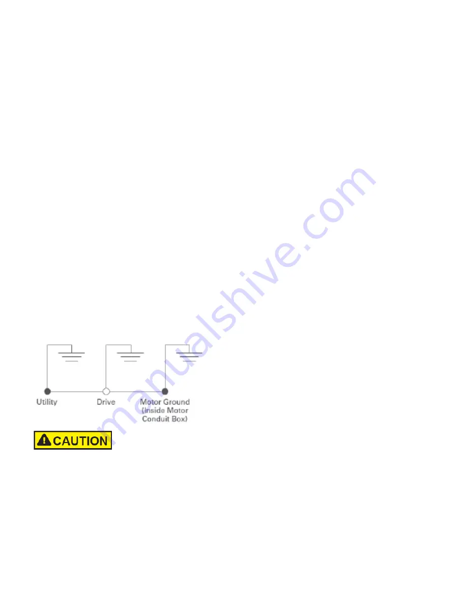
Ground wiring
•
Run motor cables in separate conduit
• DO NOT RUN CONTROL WIRES in same conduit
• Cables sized per Appendix B
• Provide dedicated wire for low impedance ground
between drive and motor. DO NOT USE conduit as
ground
Improper grounding could result in damage to the
motor and/or drive and could void warranty.
Checking the cable and motor insulation
1. Check the motor cable insulation as follows:
•
Disconnect the motor cable from terminals U,
V and W of the EVM drive and from the motor
•
Measure the insulation resistance of the motor
cable between each phase conductor as well
as between each phase conductor and the
protective ground conductor
•
The insulation resistance must be >1M ohm
2. Check the input power cable insulation as
follows:
•
Disconnect the input power cable from
terminals L1, L2 and L3 of the EVM drive and
from the utility line feeder
•
Measure the insulation resistance of the input
power cable between each phase conductor as
well as between each phase conductor and the
protective ground conductor
•
The insulation resistance must be >1M ohm
3.
Check the motor insulation as follows:
•
Disconnect the motor cable from the motor and
open any bridging connections in the motor
connection box
•
Measure the insulation resistance of each
motor winding. The measurement voltage must
equal at least the motor nominal voltage but
not exceed (1.1 * 2* Sqrt (2) X Vdc).
•
The insulation resistance must be >1M ohm
EMC Installation
Note:
All following information is strongly recommended
but is not necessary if sufficient system design
and validation has been completed.
The responsibility to meet the local system EMC limit
values and electromagnetic compatibility requirements
is the responsibility of the end user or the system
operator. This operator must also take measures to
minimize or remove emissions in the environment
concerned (see Figure below). He must also use means
to increase the interference immunity of the system
devices.
In a drive system (PDS) with frequency inverters, you
should take measures for electromagnetic compatibility
(EMC) while doing your planning, because changes or
improvements to the installation site, which are required
in the installation or while mounting, are normally
associated with additional higher costs.
The technology and system of a frequency inverter
cause the flow of high frequency leakage current during
operation. All grounding measures must therefore be
implemented with low impedance connections over a
large surface area.