D6.3.4/0715-0716/E
15
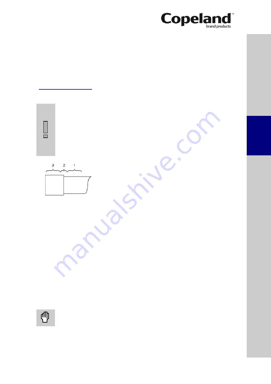
Figure 11: Brazing areas
3.2.5 Maximum allowable pressures
The maximum allowable pressures (according to EN 12693) shown on the compressor
nameplate are obligatory and must not be exceeded.
High pressure side (HP):
28.0 bar(g) (up to S/N 14K46143M & 14K031872M)
32.5 bar(g) (from S/N 14K46144M & 14K031873M onwards)
Low pressure side (LP):
22.5 bar
NOTE:
The compressor operating range may be restricted for various reasons. Check the
application range limitations in Copeland brand products Select software and on
3.3
Brazing procedure
IMPORTANT
Blockage! Compressor breakdown!
Maintain a flow of oxygen-free
nitrogen through the system at very low pressure during brazing. Nitrogen
displaces the air and prevents the formation of copper oxides in the system.
If allowed to form, the copper oxide material can later be swept through the
system and block screens such as those protecting capillary tubes, thermal
expansion valves, and accumulator oil return holes.
Contamination or moisture!
Bearing failure!
Do not remove the plugs until
the compressor is set into the unit. This minimises any entry of contaminants
and moisture.
Figure 11
shows the proper procedure for brazing the
suction and discharge shut-off valves.
The shut-off valves of the compressors can be
brazed in approximately the same manner as any copper
tube.
Recommended brazing materials: any silfos material
is recommended, preferably with a minimum of 5% silver.
However, 0% silver is acceptable.
Be sure tube fitting inner diameter and tube outer
diameter are clean prior to assembly.
Using a double-tipped torch, apply heat in area 1.
As the tube approaches brazing temperature, move the torch flame to area 2.
Heat area 2 until braze temperature is attained, moving the torch up and down and rotating
around the tube as necessary to heat the tube evenly. Add braze material to the joint while
moving the torch around the joint to flow braze material around the circumference.
After the braze material flows around the joint, move the torch to heat area 3. This will draw
the braze material down into the joint. The time spent heating area 3 should be minimal.
As with any brazed joint, overheating may be detrimental to the final result.
To disconnect:
Heat joint areas 2 and 3 slowly and uniformly until the braze material softens and the tube
can be pulled out of the fitting.
To reconnect:
Recommended brazing materials: Silfos with minimum 5% silver or silver braze used on
other compressors. Due to the different thermal properties of steel and copper, brazing
procedures may have to be changed from those commonly used.
3.4
Screens
CAUTION
Screen blocking! Compressor breakdown!
Use screens with at least
0.6 mm openings.
The use of screens finer than 30 x 30 meshes (0.6 mm openings) anywhere in the system
should be avoided with these compressors. Field experience has shown that finer mesh screens
used to protect thermal expansion valves, capillary tubes or accumulators can become
temporarily or permanently plugged with normal system debris and block the flow of either oil or
refrigerant to the compressor. Such blockage can result in compressor failure.
S
afet
y
in
struct
ion
s
P
ro
d
u
ct
d
es
cr
ipt
ion
Inst
all
atio
n
E
lec
tr
ica
l
c
o
n
n
ec
tion
S
tar
ting
up
&
o
p
er
atio
n
Ma
int
enan
c
e &
repai
r
T
ro
u
b
le
-
sho
o
ting
Dismant
ling
&
d
ispo
sa
l
Содержание Copeland 2D Series
Страница 1: ...Application Guidelines Semi Hermetic Compressors Discus K L S Series ...
Страница 5: ......


