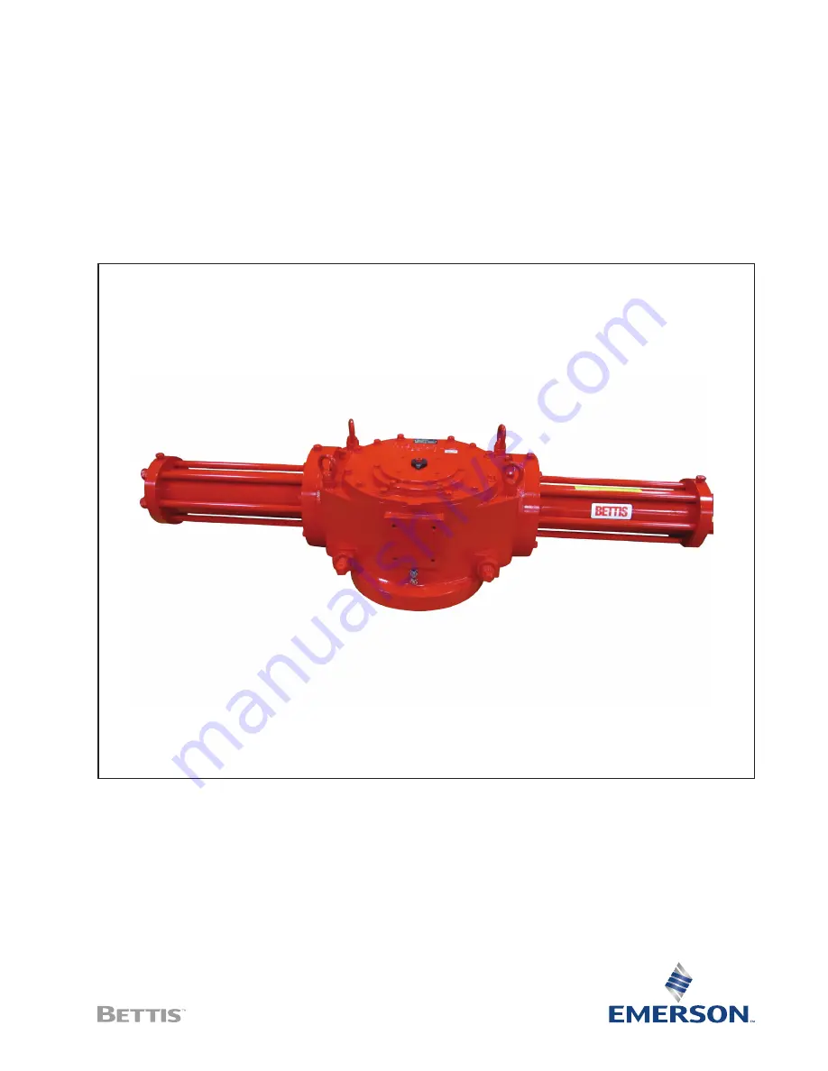
Service Instructions
124842E Rev. C
October 2015
G01 through G10 Series Hydraulic Actuators
Double-Acting with M11 Hydraulic Override Disassembly and Reassembly
Страница 1: ...Service Instructions 124842E Rev C October 2015 G01 through G10 Series Hydraulic Actuators Double Acting with M11 Hydraulic Override Disassembly and Reassembly ...
Страница 2: ......
Страница 3: ...lic Power Module Disassembly 7 2 3 H Hydraulic Override Module Disassembly 8 2 4 Drive Module Disassembly 9 Section 3 Actuator Reassembly 3 1 General Reassembly 12 3 2 Drive Module Reassembly 12 3 3 Hydraulic Power Module Reassembly 17 3 4 H Hydraulic Override Module Reassembly 19 3 5 Actuator Testing 21 Section 4 Field Conversions 4 1 Converting Double Acting to Double Acting with H Hydraulic Ove...
Страница 4: ... Table 29 6 4 G2 Tool Table 30 6 5 G3 Tool Table 30 6 6 G4 Tool Table 31 6 7 G5 Tool Table 31 6 8 G7 Tool Table 32 6 9 G8 Tool Table 32 6 10 G10 Tool Table 33 Section 7 Troubleshooting 7 1 Fault Insertion 34 7 2 Operational Test 35 Section 8 Removal and Decommissioning 8 1 Removal and Decommissioning 36 Section 9 Document Revision 37 Appendix A List of Tables 38 Appendix B List of Drawings 39 ...
Страница 5: ... accessories that will interfere with the module s that are to be worked on 1 1 5 This procedure should only be implemented by a technically competent technician who should take care to observe good workmanship practices 1 1 6 Numbers in parentheses indicate the bubble number reference number used on the Bettis assembly drawing and actuator parts list 1 1 7 This procedure is written using the stop...
Страница 6: ...tion 1 3 1 Products supplied by Emerson in its as shipped condition are intrinsically safe if the instructions contained within this service instruction are strictly adhered to and executed by well trained equipped prepared and competent personnel WARNING READ WARNING MESSAGES CAREFULLY For the protection of personnel working on Bettis actuators this procedure should be reviewed and implemented fo...
Страница 7: ...d extension retainer nut tool refer to the following table NOTE These tools are required only when extension rod assembly 1 50 or 9 50 is removed or when a new extension rod assembly is installed Table 1 Actuator Model and Part Number ACTUATOR MODEL BETTIS PART NUMBER ACTUATOR MODEL BETTIS PART NUMBER G01 None required G5 G7 117369 G2 123616 G8 G10 117368 G3 G4 117370 1 5 3 Non hardening thread se...
Страница 8: ...uct Engineering 1 7 2 1 All temperature service 20 F to 350 F 28 9 C to 176 6 C use Shell Tellus S2 V Grade 32 automatic transmission fluid or an Emerson approved fluid 1 8 General Tool Information 1 8 1 Tools All tools hexagons are American Standard inch Large adjustable wrench two 2 large screwdrivers Allen wrench set set of open box end wrenches rubber or leather mallet torque wrench up to 1600...
Страница 9: ...ten have scale and other debris in them and these lines should be purged of all foreign material NOTE Scale and debris can damage control valves solenoids seals etc 1 11 Actuator Start up 1 11 1 Prestart up checks 1 Inspect to ensure the unit has been mounted onto valve properly Gear flange mounting bolts stem key setscrew s are installed and secured 2 No tubing damaged or accessories dislodged du...
Страница 10: ...imes may be obtained by using one or more of the following 1 Larger supply lines 2 Larger control valve 3 Higher supply pressure 4 Quick exhaust valves Not to exceed maximum operating pressure of actuator or control components 1 11 6 Slower operating times may be obtained using flow control valves to meter the exhaust Excessive exhaust flow metering may cause erratic operation 1 12 Actuator Operat...
Страница 11: ...nd disassembled separate to the actuator refer to Section 5 Module Removal and Installation NOTE Use a means of capturing the hydraulic fluid that will be lost during the removal or disassembly of the hydraulic power module or H hydraulic override module Use a bucket tub large container etc 2 1 3 To ensure correct reassembly that is with hydraulic power module or H hydraulic override module on sam...
Страница 12: ...nner end cap 3 10 off the piston rod 3 40 NOTE The piston rod 3 40 removal as outlined in step 2 2 15 is only required when the piston rod is being replaced or when the drive module is to be disassembled 2 2 15 Unscrew and remove piston rod 3 40 from the drive module 2 3 H Hydraulic Override Module Disassembly NOTE Review Section 2 steps 2 1 1 through 2 1 3 general disassembly before proceeding wi...
Страница 13: ...bly NOTE Review Section 2 steps 2 1 1 through 2 1 3 general disassembly before proceeding with drive module disassembly 2 4 1 If not already removed remove piston rod 3 40 from drive module 2 4 2 Mark stop screws 1 180 left and right The setting of stop screws 1 180 should be checked and setting recorded before stop screws are loosened or removed NOTE Stop screws will be removed later in this proc...
Страница 14: ...ing 1 10 NOTE Groove pins 1 130 will remain in housing cover 1 20 when housing cover is removed from housing 1 10 Groove pins 1 130 should not be removed from housing cover 1 20 unless they are damaged and require new replacements 2 4 14 Refer to assembly drawing page 2 of 2 Detail B Remove guide bar 1 90 from housing 1 10 2 4 15 Remove top yoke pin thrust bearing 2 10 from the top of the yoke pin...
Страница 15: ...oved 2 4 25 Remove the remaining spherical washers 1 40 and 9 40 from guide block 1 30 2 4 26 Unscrew and remove two stop screw nuts 1 190 from stop screws 1 180 2 4 27 Unscrew and remove two stop screws 1 180 from housing 1 10 2 4 28 Housing 1 10 vent check assembly removal as follows 2 4 28 1 G01 G2 and G3 housings 1 10 unscrew and remove one vent check assembly 13 from the front of housing 1 10...
Страница 16: ...ng or flaking coating CAUTION REPLACE WORN PARTS Actuator parts that reflect any of the above listed characteristics should be replaced with new parts 3 1 4 Before installation coat all moving parts with a complete film of lubricant Coat all seals with a complete film of lubricant before installing into seal grooves NOTE The parts and seals used in the drive module will be assembled using lubrican...
Страница 17: ...rical washer 1 40 3 2 6 Install extension retainer nut 1 60 over extension rod assembly 1 50 and screw into guide block 1 30 3 2 7 Tighten extension retainer nut assembly 1 60 until extension rod assembly 1 50 cannot move Back off the extension retainer nut assembly 1 60 just enough to allow the extension rod assembly 1 50 to move freely 3 2 8 Lubricate two spherical washers 9 40 and one extension...
Страница 18: ...e guide block bushings 2 30 and install onto top and bottom sides of guide block 1 30 NOTE The guide block 1 30 should be already preassembled with extension rod assembly and associated parts assembled in the guide block 3 2 17 Install guide block 1 30 with yoke guide block bushings 2 30 between arms of yoke 1 70 3 2 18 Install O ring seal 2 50 into inner diameter O ring groove in the bottom of ho...
Страница 19: ...hreads of hex cap screws 1 110 Reference assembly drawing note number 9 3 2 29 Install hex cap screws 1 110 with lockwashers 1 115 through housing cover 1 20 and into housing 1 10 NOTE Leave hex cap screws 1 110 finger tight do not tighten Do this step only if groove pins 1 130 have been pulled or if the pins are being replaced Drive groove pins 1 130 through housing cover 1 20 and into housing 1 ...
Страница 20: ...crews 1 160 3 2 40 Install and tighten hex cap screws 1 160 with lockwashers through yoke cover 1 150 and into housing cover 1 20 3 2 41 Vent check assembly installation as follows 3 2 41 1 For G01 G2 and G3 housing 1 10 using pipe sealant install one vent check assembly 13 into the front of housing 1 10 3 2 41 2 For G01 G2 and G3 housing cover 1 20 using pipe sealant install one vent check assemb...
Страница 21: ... in piston rod 3 40 and retain with one retainer ring 3 60 3 3 6 Apply fluid to the bore of cylinder 3 70 3 3 7 Coat one piston bearing 4 45 with fluid and install into external seal groove of piston 3 30 3 3 8 Install piston 3 30 with piston rod 3 40 into cylinder 3 70 and leave the inner most piston seal groove outside of the cylinder CAUTION CORRECTLY INSTALL PISTON SEAL Install the piston seal...
Страница 22: ...ap 3 80 into open end of cylinder 3 70 NOTE The pressure inlet ports of the inner and outer end caps should be positioned in the same position as recorded in Section 2 step 2 2 1 3 3 20 Install the remaining tie bars 3 20 through outer end cap 3 80 and into inner end cap 3 10 Refer to the following CAUTION CAUTION CORRECTLY ASSEMBLE TIE BARS Assemble tie bars 3 20 into inner end cap 3 10 with a mi...
Страница 23: ... fluid to the bore of cylinder 7 70 3 4 7 Coat one piston bearing 8 45 with fluid and install into external seal groove of piston 7 30 3 4 8 Install piston 7 30 with piston rod 7 40 into cylinder 7 70 and leave the inner most piston seal groove out side of the cylinder 3 4 9 Coat one piston seal 8 60 with fluid and install into external seal groove of piston 7 30 CORRECTLY INSTALL PISTON SEAL Inst...
Страница 24: ...ld be positioned in the same position as recorded in Section 2 step 2 2 1 3 4 20 Install the remaining tie bars 7 20 through outer end cap 7 80 and into inner end cap 7 10 Refer to the following CAUTION CORRECTLY ASSEMBLE TIE BARS Assemble tie bars 7 20 into inner end cap 7 10 with a minimum engagement of one tie bar thread diameter Ensure that three to four threads are equally exposed beyond the ...
Страница 25: ... both sides of the piston simultaneously for a period of two 2 minutes NOTE If any leakage occurs during step 3 5 6 the actuator must be disassembled and the cause of leakage must be determined and corrected 3 5 7 If an actuator was disassembled and repaired the above testing must be performed again 3 5 8 Shell Pressure Test Optional pressure test could be performed on the actuator by applying pre...
Страница 26: ... with H Hydraulic Override Module 4 1 1 Remove blind end cap per steps 4 1 1 1 and 4 1 1 2 4 1 1 1 Remove hex cap screws 5 20 with spring lockwashers 5 30 from blind end cap 5 10 4 1 1 2 Remove blind end cap 5 10 from end of housing 1 10 4 1 2 Install Powr Swivl module per Section 5 6 4 1 3 Install the H hydraulic override module onto drive module per Section 5 step 5 4 ...
Страница 27: ...move hex cap screws 3 115 with lockwashers 3 110 from inner end cap 3 10 5 1 4 Remove hex nuts 3 105 from hex cap screws 3 100 5 1 5 Remove Hydraulic Power Module from actuator housing 1 10 5 2 Hydraulic Power Module Installation NOTE ReviewSection3 1generalreassemblybeforeproceedingwithhydraulicpowermoduleinstallation 5 2 1 Check to verify if O ring seal 4 90 is properly seated in its seal groove...
Страница 28: ...5 5 2 7 Install hex cap screws 3 115 with lockwashers 3 110 through inner end cap 3 10 and screw into housing 1 10 5 2 8 Install lock washers 3 110 onto hex cap screws 3 100 5 2 9 Refer to assembly drawing page 2 of 2 Detail F Install hex cap screws 3 100 with lockwashers 3 110 through inner end cap 3 10 and housing 1 10 5 2 10 Install and tighten hex nuts 3 105 onto hex cap screws 3 100 5 2 11 Us...
Страница 29: ... through outer end cap 7 80 and screw piston rod 7 40 into guide block 1 30 WARNING DO NOT CROSS THREAD When screwing piston rod into guide block 1 30 make certain that the piston rod and guide block threads do not cross thread 5 4 4 G2 THROUGH G10 MODEL ACTUATORS 5 4 4 1 Align piston rod 7 40 with extension rod assembly 1 50 5 4 4 2 Using a male square drive extension go through outer end cap 7 8...
Страница 30: ...c rod through the hole where the blind end cap was removed and by pushing on the guide block 5 5 2 Refer to assembly drawing page 2 of 2 Detail B Use Bettis tool part number as listed in chart in section 1 step 1 2 1 to remove retainer nut assembly 1 60 from the guide block 1 30 CAUTION DO NOT DROP SPHERICAL WASHERS When removing rod extension assembly from guide block be careful not to drop one o...
Страница 31: ...e of guide block 1 30 5 6 4 Install second spherical washer 1 40 over threaded end of extension rod assembly 1 50 NOTE The spherical side of the washer will go on the extension rod assembly facing the head of the extension rod assembly 5 6 5 Install extension rod assembly 1 50 into right of guide block 1 30 and up against the first spherical washer 1 40 5 6 6 Install extension retainer nut assembl...
Страница 32: ...bs 26 29 43 N A N A N A N A N A 2 0 Dia Power Module Kg 11 7 13 19 5 N A N A N A N A N A 3 Lbs 27 30 45 N A N A N A N A N A 2 2 Dia Power Module Kg 12 2 13 6 20 4 N A N A N A N A N A 3 Lbs 28 31 48 71 N A N A N A N A 2 5 Dia Power Module Kg 12 7 14 1 21 7 32 N A N A N A N A 3 Lbs 29 35 48 84 5 N A N A N A N A 3 0 Dia Power Module Kg 13 15 8 21 7 38 N A N A N A N A 3 Lbs 32 38 52 83 160 N A N A N A...
Страница 33: ... A N A N A 38 N A N A N A N A 7 Lbs N A N A N A N A 173 N A N A N A 5 0 Dia H Power Module Kg N A N A N A N A 78 N A N A N A 7 Lbs N A N A N A N A N A 303 N A N A 6 0 Dia H Power Module Kg N A N A N A N A N A 137 N A N A 7 Lbs N A N A N A N A N A N A 485 N A 7 0 Dia H Power Module Kg N A N A N A N A N A N A 220 N A 7 Lbs N A N A N A N A N A N A N A 808 9 0 Dia H Power Module Kg N A N A N A N A N A...
Страница 34: ...x Nuts Socket 3 115 7 115 9 16 4 Hex Cap Screws Socket 3 120 7 120 9 16 Sq 1 Pipe Plug Square Head Open End or Adjustable 13 3 4 2 Vent Check Assembly Open End 6 5 G3 Tool Table Table 9 G3 Tool Style and Wrench Size ITEM NO WRENCH SIZE ITEM QTY LOCATION OR DESCRIPTION RECOMMENDED TOOL STYLE 1 110 9 16 8 Cover Screws Socket 1 160 9 16 4 Yoke Cover Screws Socket 1 180 1 2 Sq 2 Stop Screws Open End o...
Страница 35: ...Socket 3 115 7 115 3 4 4 Hex Cap Screws Socket 3 120 7 120 5 8 Sq 1 Pipe Plug Square Head Open End or Socket 13 3 4 2 Vent Check Assembly Open End 6 7 G5 Tool Table Table 11 G5 Tool Style and Wrench Size ITEM NO WRENCH SIZE ITEM QTY LOCATION OR DESCRIPTION RECOMMENDED TOOL STYLE 1 110 3 4 8 Cover Screws Socket 1 120 3 4 4 Yoke Cover Screws Socket 1 160 9 16 6 Hex Cap Screws Socket 1 180 3 4 Sq 2 S...
Страница 36: ...tandard Hex Nuts Socket 3 115 7 115 15 16 8 Hex Cap Screws Socket 3 120 7 120 15 16 1 Pipe Plug Hex Head Socket 13 3 4 2 Vent Check Assembly Open End 6 9 G8 Tool Table Table 13 G8 Tool Style and Wrench Size ITEM NO WRENCH SIZE ITEM QTY LOCATION OR DESCRIPTION RECOMMENDED TOOL STYLE 1 110 3 4 12 Cover Screws Socket 1 120 3 4 4 Yoke Cover Screws Socket 1 160 9 16 8 Hex Cap Screws Socket 1 180 1 1 4 ...
Страница 37: ...1 110 3 4 16 Cover Screws Socket 1 120 3 4 4 Yoke Cover Screws Socket 1 160 9 16 8 Hex Cap Screws Socket 1 180 1 1 2 2 Stop Screws Open End or Adjustable 3 40 7 40 3 4 Sq 1 Piston Rod Male Drive 3 90 7 90 1 7 8 8 Hex Nuts Socket 3 100 7 100 1 1 8 8 Hex Cap Screws Socket 3 105 7 105 1 1 8 8 Standard Hex Nuts Socket 3 115 7 115 1 1 8 8 Hex Cap Screws Socket 3 120 7 120 15 16 1 Pipe Plug Hex Head Ope...
Страница 38: ...ousing during maintenance Disassemblecylinderassemblytoremovedebris andreassemblecylinderassembleasnecessary Defective valve Consultthevalvemanufacturer sdocumentation Apparent lack of torque Inadequate supply pressure Ensure supply pressure is above the minimum operating pressure of the actuator and that output torque produced at supply pressure exceeds valve torque demand Incorrect speed control...
Страница 39: ...uator valve Upon successful completion of the above described full stroke test procedure the test coverage can be considered 99 7 2 2 Partial Stroke Test when requested The partial stroke test on line can be performed to improve the PFDAVG value and to satisfy PFDAVG average probability of failure on demand value A typical partial stroke value is 15 of the stroke and the recommended test interval ...
Страница 40: ...urn off the power medium and bleed off all pressure first including storage tank if present Next bleed off pilot pressure and disconnect pneumatic pressure supply pilot tubing and electrical wiring if equipped Before starting the disassembly a large area should be created around the actuator to allow any kind of movement Separate the parts comprising the actuator according to their nature e g meta...
Страница 41: ...ument Revision Section 9 Document Revision Table 16 Revision Overview ECN DATE REVISION STATUS BY DATE Released April 2002 A B Cornelius April 2002 19110 July 2006 B UPDATED C Ross July 2006 VAWCO2794 October 2015 C UPDATED C Rico October 2015 Signatures on file Bettis Houston Texas ...
Страница 42: ...ride System Fluid Volume Table 28 Table 6 Module Weights By Item Number and Actuator Housing Size 28 Table 7 G01 Tool Style and Wrench Size 29 Table 8 G2 Tool Style and Wrench Size 30 Table 9 G3 Tool Style and Wrench Size 30 Table 10 G4 Tool Style and Wrench Size 31 Table 11 G5 Tool Style and Wrench Size 31 Table 12 G7 Tool Style and Wrench Size 32 Table 13 G8 Tool Style and Wrench Size 32 Table 1...
Страница 43: ...October 2015 Service Instructions 124842E Rev C 39 Appendix Appendix Appendix B List of Drawings B 1 Part No 115916 GXXXX X H Hydraulic Assembly Drawing Sheet 1 of 2 ...
Страница 44: ...October 2015 Service Instructions 124842E Rev C 40 Appendix Appendix B 2 Part No 115916 GXXXX X H Hydraulic Assembly Drawing Sheet 2 of 2 ...
Страница 45: ...October 2015 Service Instructions 124842E Rev C 41 Appendix Appendix B 3 Part No 126567 M11 Assembly Drawing Sheet 1 of 5 ...
Страница 46: ...October 2015 Service Instructions 124842E Rev C 42 Appendix Appendix B 4 Part No 126567 M11 Assembly Drawing Sheet 2 of 5 ...
Страница 47: ...October 2015 Service Instructions 124842E Rev C 43 Appendix Appendix B 5 Part No 126567 M11 Assembly Drawing Sheet 3 of 5 ...
Страница 48: ...October 2015 Service Instructions 124842E Rev C 44 Appendix Appendix B 6 Part No 126567 M11 Assembly Drawing Sheet 4 of 5 ...
Страница 49: ...October 2015 Service Instructions 124842E Rev C 45 Appendix Appendix B 7 Part No 126567 M11 Assembly Drawing Sheet 5 of 5 ...
Страница 50: ...October 2015 Service Instructions 124842E Rev C 46 Appendix Appendix B 8 Part No 121107 M11S S G4 G8 Fire Safe Remote Mount Assembly Drawing Sheet 1 of 2 ...
Страница 51: ...October 2015 Service Instructions 124842E Rev C 47 Appendix Appendix B 9 Part No 121107 M11S S G4 G8 Fire Safe Remote Mount Assembly Drawing Sheet 2 of 2 ...
Страница 52: ......
Страница 53: ...ongmeadow Business Estate East P O Box 6908 Greenstone 1616 Modderfontein Extension 5 South Africa T 27 11 451 3700 EUROPE Holland Fasor 6 Székesfehérvár 8000 Hungary T 36 22 53 09 50 Strada Biffi 165 29017 Fiorenzuola d Arda PC Italy T 39 0523 944 411 www emerson com bettis 2018 Emerson All rights reserved The Emerson logo is a trademark and service mark of Emerson Electric Co BettisTM is a mark ...